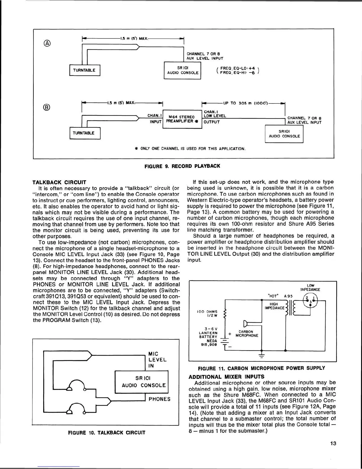
FIGURE
9.
RECORD PLAYBACK
,
lTl.5~~~m~y
,
@
CHANNEL
7
OR
8
AUX
LEVEL
INPUT
TURNTABLE
SR
lOl
FREQ.
EQ-LO:
+4
AUDIO
CONSOLE
(
FREQ.
EQ-HI:
-6
)
1.5
m
(5') MAX.
3
PUP
TO
305
m
(1000')
TALKBACK CIRCUIT
It is often necessary to provide a "talkback" circuit (or
"intercom," or
"com line") to enable the Console operator
to instruct or cue performers, lighting control, announcers,
etc. It also enables the operator to avoid hand or light sig-
nals which may not be visible during a performance. The
talkback circuit requires the use of one input channel, re-
moving that channel from use by performers. Note too that
the monitor circuit is being used, preventing its use for
other purposes.
To use low-impedance (not carbon) microphones, con-
nect the microphone of a single headset-microphone to a
Console MIC LEVEL lnput Jack (33) (see Figure 10, Page
13). Connect the headset to the front-panel PHONES Jacks
(8). For high-impedance headphones, connect to the rear-
panel MONITOR LlNE LEVEL Jack (30). Additional head-
sets may be connected through
"Y"
adapters to the
PHONES or MONITOR LlNE LEVEL Jack. If additional
microphones are to be connected,
"Y"
adapters (Switch-
craft
391Q13,391Q53 or equivalent) should be used to con-
nect these to the MIC LEVEL lnput Jack. Depress the
MONITOR Switch (12) for the
talkback channel and adjust
the MONITOR Level Control (10) as desired. Do not depress
the PROGRAM Switch (13).
@
CHAN.
I
I
INPUT
MIC
LEVEL
IN
L
,
SR
lOl
AUDIO CONSOLE
I
PHONES
If this set-up does not work, and the microphone type
being used is unknown, it is possible that it is a carbon
microphone. To use carbon microphones such as found in
Western Electric-type operator's headsets, a battery power
supply is required to power the microphone (see Figure 11,
Page 13). A common battery may be used for powering a
number of carbon microphones, though each microphone
requires its own 100-ohm resistor and Shure A95 Series
line matching transformer.
Should a large number of headphones be required, a
power amplifier or headphone distribution amplifier should
be inserted in the headphone circuit between the MONI-
TOR LlNE LEVEL Output (30) and the distribution amplifier
input.
M64
STEREO
PREAMPLIFIER
*
CHAN.
I
LOW
LEVEL
OUTPUT
AUX
LEVEL
INPUT
TURNTABLE
FIGURE
11.
CARBON MICROPHONE POWER SUPPLY
ADDITIONAL MIXER INPUTS
Additional microphone or other source inputs may be
obtained using a high gain, low noise, microphone mixer
such as the Shure
M68FC. When connected to a MIC
LEVEL lnput Jack
(33), the M68FC and SR101 Audio Con-
sole will provide a total of 11 inputs (see Figure
12A, Page
14). (Note that adding a mixer at an lnput Jack converts
that channel to a submaster control; the total number of
inputs will thus be the mixer total plus the Console total
-
FIGURE
10.
TALKBACK CIRCUIT
8
-
minus 1 for the submaster.)
SR
lOl
AUDIO
CONSOLE
LOW
IMPEDANCE
100
OHMS
1/2
W
?#
ONLY
ONE
CHANNEL
IS
USED
FOR
THIS
APPLICATION.
D
3-6V
CARBON
LANTERN
+
MICROPHONE
BATTERY
,
NEDA
915
,908
-
-
-
-
 Loading...