output of one Console, the channel inputs of both units
will be routed through the operative Console. This type of
system is termed "redundant," that is, the reliability of the
system is enhanced through parallel functioning devices.
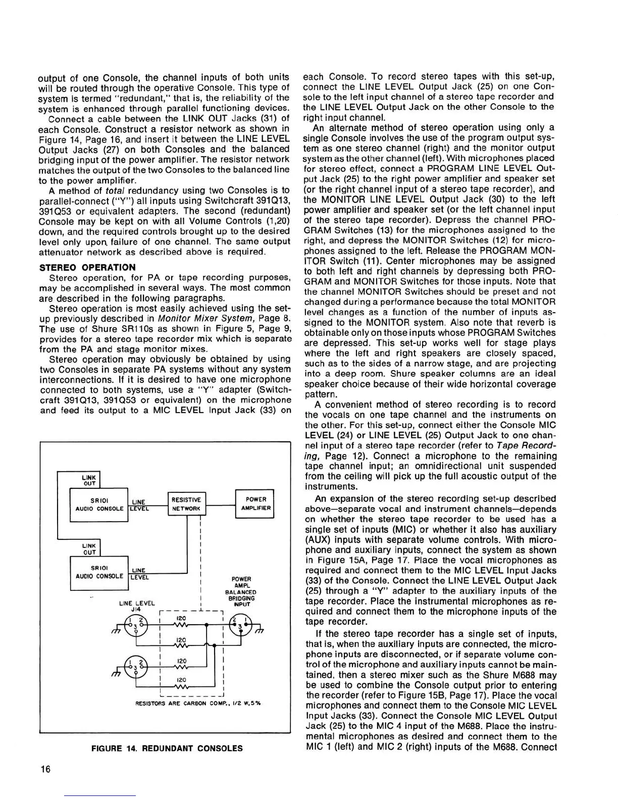
Connect a cable between the LlNK OUT Jacks (31) of
each Console. Construct a resistor network as shown in
Figure 14, Page 16, and insert it between the
LlNE LEVEL
Output Jacks (27) on both Consoles and the balanced
bridging input of the power amplifier. The resistor network
matches the output of the two Consoles to the balanced line
to the power amplifier.
A method of total redundancy using two Consoles is
to
parallel-connect
("Y")
all inputs using Switchcraft 391Q13,
391Q53
or equivalent adapters. The second (redundant)
Console may be kept on with all Volume Controls
(1,20)
down, and the required controls brought up to the desired
level only upon. failure of one channel. The same output
attenuator network as described above is required.
STEREO OPERATION
Stereo operation, for PA or tape recording purposes,
may be accomplished in several ways. The most common
are described in the following paragraphs.
Stereo operation is most easily achieved using the set-
up previously described in Monitor Mixer System, Page 8.
The use of Shure
SRllOs as shown in Figure 5, Page 9,
provides for a stereo tape recorder mix which is separate
from the PA and stage monitor mixes.
Stereo operation may obviously be obtained by using
two Consoles in separate PA systems without any system
interconnections. If it is desired to have one microphone
connected to both systems, use
a.
"Y"
adapter (Switch-
craft 391 Q13, 391 (2.53 or equivalent) on the microphone
and feed its output to a MIC LEVEL
lnput Jack (33) on
FIGURE
14.
REDUNDANT CONSOLES
16
I
each Console. To record stereo tapes with this set-up,
connect the
LlNE LEVEL Output Jack (25) on one Con-
sole to the left input channel of a stereo tape recorder and
the
LlNE LEVEL Output Jack on the other Console to the
right input channel.
An alternate method of stereo operation using only a
single Console involves the use of the program output sys-
tem as one stereo channel (right) and the monitor output
system as the other channel (left). With microphones placed
for stereo effect, connect a PROGRAM
LlNE LEVEL Out-
put Jack (25) to the right power amplifier and speaker set
(or the right channel input of a stereo tape recorder), and
the MONITOR LlNE LEVEL Output Jack (30) to the left
power amplifier and speaker set (or the left channel input
of the stereo tape recorder). Depress the channel PRO-
GRAM Switches (13) for the microphones assigned to the
right, and depress the MONITOR Switches (12) for micro-
phones assigned to the left. Release the PROGRAM MON-
ITOR Switch (11). Center microphones may be assigned
to both left and right channels by depressing both PRO-
GRAM and MONITOR Switches for those inputs. Note that
the channel MONITOR Switches should be preset and not
changed during a performance because the total MONITOR
level changes as a function of the number of inputs as-
signed to the MONITOR system. Also note that reverb is
obtainable only on those inputs whose PROGRAM Switches
are depressed. This set-up works well for stage plays
where the left and right speakers are closely spaced,
such as to the sides of a narrow stage, and are projecting
into a deep room. Shure speaker columns are an ideal
speaker choice because of their wide horizontal coverage
pattern.
A convenient method of stereo recording is to record
the vocals on one tape channel and the instruments on
the other. For this set-up, connect either the Console MIC
LEVEL (24) or
LlNE LEVEL (25) Output Jack to one chan-
nel input of a stereo tape recorder (refer to Tape Record-
ing, Page 12). Connect a microphone to the remaining
tape channel input; an omnidirectional unit suspended
from the ceiling will pick up the full acoustic output of the
instruments.
An expansion of the stereo recording set-up described
above-separate vocal and instrument channels-depends
on whether the stereo tape recorder to be used has a
single set of inputs (MIC) or whether it also has auxiliary
(AUX) inputs with separate volume controls. With micro-
phone and auxiliary inputs, connect the system as shown
in Figure
15A, Page 17. Place the vocal microphones as
required and connect them to the MIC LEVEL lnput Jacks
(33) of the Console. Connect the LlNE LEVEL Output Jack
(25) through a
"Y"
adapter to the auxiliary inputs of the
tape recorder. Place the instrumental microphones as re-
quired and connect them to the microphone inputs of the
tape recorder.
If the stereo tape recorder has a single set of inputs,
that is, when the auxiliary inputs are connected, the micro-
phone inputs are disconnected, or if separate volume con-
trol of the microphone and auxiliary inputs cannot be
main.-
tained, then a stereo mixer such as the Shure M688 may
be used to combine the Console output prior to entering
the recorder (refer to Figure
15B, Page 17). Place the vocal
microphones and connect them to the Console MIC LEVEL
lnput Jacks (33). Connect the Console MIC LEVEL Output
Jack (25) to the MIC 4 input of the
M688. Place the instru-
mental microphones as desired and connect them to the
MIC 1 (left) and MIC 2 (right) inputs of the
M688. Connect
r
LlNK
OUT
SR lOl
AUDIO CONSOLE
J
POWER
AMPLIFIER
LINE
LEVEL
I
RESISTIVE
NETWORK
I
I
I
I
I
I
I
LINK
OUT
SRlOl
LlNE
AUDIO CONSOLE
LEVEL
I
I
POWER
AMPL
I
BALANCED
I
BRIDGING
LINE LEVEL
I
INPUT
RESISTORS ARE CARBON COMP..
112 W,5%
 Loading...