sions given should be followed to provide adequate cable
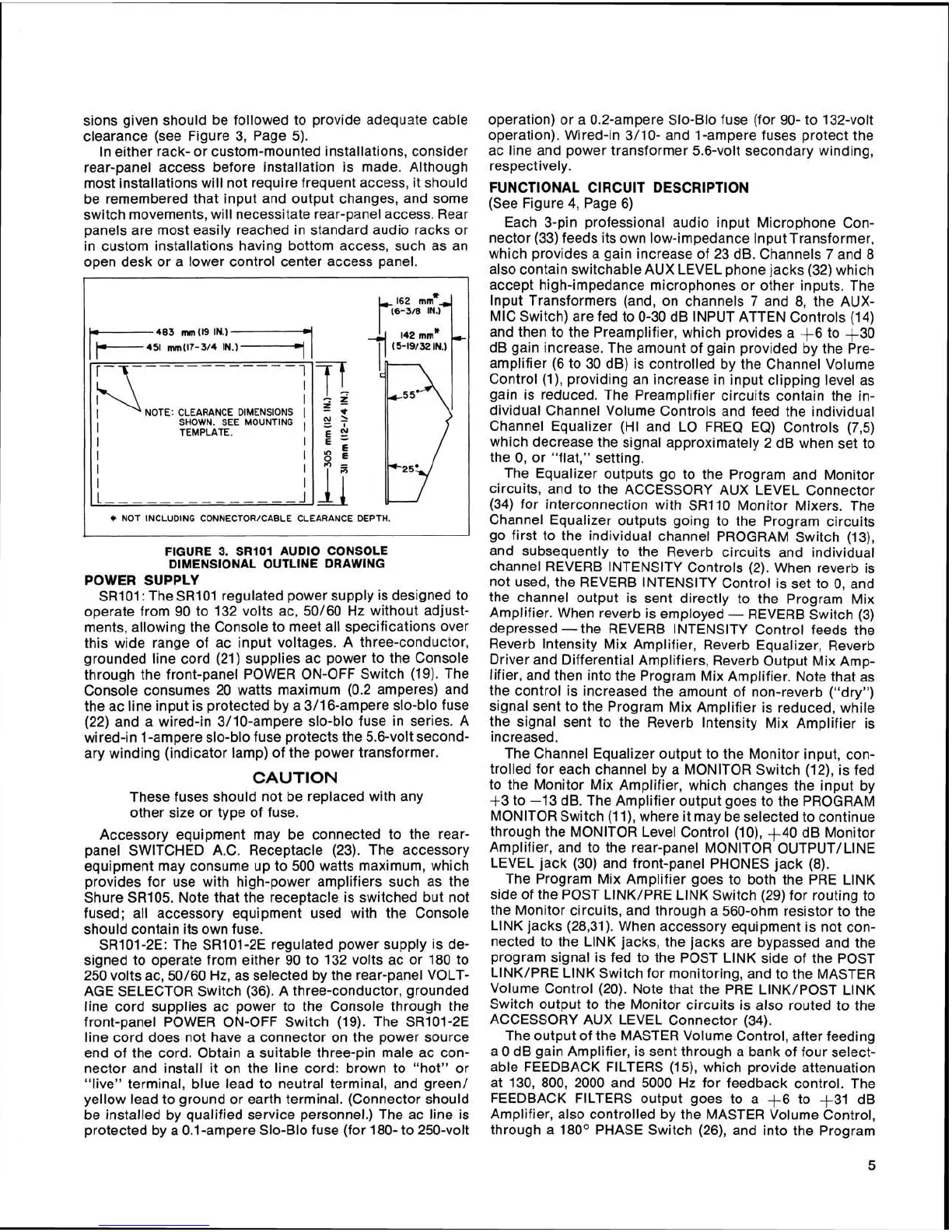
clearance (see Figure 3, Page 5).
In either rack- or custom-mounted installations, consider
rear-panel access before installation is made. Although
most installations will not require frequent access, it should
be remembered that input and output changes, and some
switch movements, will necessitate rear-panel access. Rear
panels are most easily reached in standard audio racks or
in custom installations having bottom access, such as an
open desk or a lower control center access panel.
,
.
NOTE: CLEARANCE DIMENSIONS
I
SHOWN. SEE MOUNTING
TEMPLATE.
I
I
I
I
*
NOT INCLUDING CONNECTOR/CABLE CLEARANCE
DEPTH.
I
-
--
-
FIGURE
3.
SRlOl AUDIO CONSOLE
DIMENSIONAL OUTLINE DRAWING
POWER SUPPLY
SR101: The SR101 regulated power supply is designed to
operate from 90 to 132 volts ac,
50/60 Hz without adjust-
ments, allowing the Console to meet all specifications over
this wide range of ac input voltages. A three-conductor,
grounded line cord (21) supplies ac power to the Console
through the front-panel POWER ON-OFF Switch (19). The
Console consumes 20 watts maximum (0.2 amperes) and
the ac line input is protected by a
3/16-ampere slo-blo fuse
(22) and a wired-in
3/10-ampere slo-blo fuse in series. A
wired-in 1-ampere slo-blo fuse protects the 5.6-volt second-
ary winding (indicator lamp) of the power transformer.
CAUTION
These fuses should not be replaced with any
other size or type of fuse.
Accessory equipment may be connected to the
rear-
panel SWITCHED A.C.
Receptacle (23). The accessory
equipment may consume up to 500 watts maximum, which
provides for use with high-power amplifiers such as the
Shure
SR105. Note that the receptacle is switched but not
fused; all accessory equipment used with the Console
should contain its own fuse.
SR101-2E: The SR101-2E regulated power supply is de-
signed to operate from either 90 to 132 volts ac or 180 to
250 volts ac,
50/60 Hz, as selected by the rear-panel VOLT-
AGE SELECTOR Switch (36). A three-conductor, grounded
line cord supplies ac power to the Console through the
front-panel POWER ON-OFF Switch (19). The
SR101-2E
line cord does not have a connector on the power source
end of the cord. Obtain a suitable three-pin male ac con-
nector and install it on the line cord: brown to "hot" or
"live" terminal, blue lead to neutral terminal, and green/
yellow lead to ground or earth terminal. (Connector should
be installed by qualified service personnel.) The ac line is
protected by a 0.1-ampere Slo-Blo fuse (for 180- to 250-volt
operation) or a 0.2-ampere Slo-Blo fuse (for 90- to 132-volt
operation). Wired-in
3/10- and 1-ampere fuses protect the
ac line and power transformer 5.6-volt secondary winding,
respectively.
FUNCTIONAL CIRCUIT DESCRIPTION
(See Figure 4, Page 6)
Each 3-pin professional audio input Microphone Con-
nector (33) feeds its own low-impedance lnput Transformer,
which provides a gain increase of 23 dB. Channels
7
and 8
also contain switchable AUX LEVEL phone jacks (32) which
accept high-impedance microphones or other inputs. The
lnput Transformers (and, on channels
7
and 8, the AUX-
MIC Switch) are fed to 0-30 dB INPUT ATTEN Controls (14)
and then to the Preamplifier, which provides a
A6 to $30
dB gain increase. The amount of gain provided by the Pre-
amplifier (6 to 30 dB) is controlled by the Channel Volume
Control
(I), providing an increase in input clipping level as
gain is reduced. The Preamplifier circuits contain the in-
dividual Channel Volume Controls and feed the individual
Channel Equalizer (HI and LO FREQ EQ) Controls
(73)
which decrease the signal approximately
2
dB when set to
the 0, or "flat," setting.
The Equalizer outputs go to the Program and Monitor
circuits, and to the ACCESSORY AUX LEVEL Connector
(34) for interconnection with
SR110 Monitor Mixers. The
Channel Equalizer outputs going to the Program circuits
go first to the individual channel PROGRAM Switch
(13),
and subsequently to the Reverb circuits and individual
channel REVERB INTENSITY Controls (2). When reverb is
not used, the REVERB INTENSITY Control is set to 0, and
the channel output is sent directly to the Program Mix
Amplifier. When reverb is employed
-
REVERB Switch (3)
depressed
-
the REVERB INTENSITY Control feeds the
Reverb Intensity Mix Amplifier, Reverb Equalizer, Reverb
Driver and Differential Amplifiers, Reverb Output Mix Amp-
lifier, and then into the Program Mix Amplifier. Note that as
the control is increased the amount of non-reverb ("dry")
signal sent to the Program Mix Amplifier is reduced, while
the signal sent to the Reverb lntensity Mix Amplifier is
increased.
The Channel Equalizer output to the Monitor input, con-
trolled for each channel by a MONITOR Switch
(12), is fed
to the Monitor Mix Amplifier, which changes the input by
+3 to -13 dB. The Amplifier output goes to the PROGRAM
MONITOR Switch (1
I), where it may be selected to continue
through the MONITOR Level Control
(lo), +40 dB Monitor
Amplifier, and to the rear-panel MONITOR
OUTPUT/LINE
LEVEL jack (30) and front-panel PHONES jack (8).
The Program Mix Amplifier goes to both the PRE LlNK
side of the POST
LINK/PRE LlNK Switch (29) for routing to
the Monitor circuits, and through a 560-ohm resistor to the
LlNK jacks
(28,31). When accessory equipment is not con-
nected to the LlNK jacks, the jacks are bypassed and the
program signal is fed to the POST LlNK side of the POST
LINK/PRE LINK Switch for monitoring, and to the MASTER
Volume Control (20). Note that the PRE
LINK/POST LlNK
Switch output to the Monitor circuits is also routed to the
ACCESSORY AUX LEVEL Connector (34).
The output of the MASTER Volume Control, after feeding
a
0 dB gain Amplifier, is sent through a bank of four select-
able FEEDBACK FILTERS
(15), which provide attenuation
at 130, 800, 2000 and 5000 Hz for feedback control. The
FEEDBACK FILTERS output goes to a
+6 to +31 dB
Amplifier, also controlled by the MASTER Volume Control,
through a
180' PHASE Switch (26), and into the Program
 Loading...