2. Set all front-panel switches to off (out) and all con-
trols to
0. Set rear-panel PHASE Switch (26) to 0'.
3. Connect desired PROGRAM OUTPUT/LINE LEVEL
Connector
(25,27) to power amplifier input connect-
ing cable. (NOTE: Shure
SR105 Power Amplifiers
are supplied with audio connecting cables.) If Console
output is to be fed to another mixer or tape recorder
microphone input, use PROGRAM
OUTPUT/MIC
LEVEL Connector (24). If desired, connect mono-
phonic or stereo headphones to front-panel PHONES
Jack (8). Connect speakers to power amplifier.
4. Connect one or more low-impedance microphones to
rear-panel
INPUTS/MICROPHONE LEVEL Connector
(33). Any high-quality dynamic, ribbon or condenser
low-impedance microphone may be used. Connect
high-impedance microphones or auxiliary high-level
sources to
INPUTS/AUX. LEVEL Connectors (32) in
channels 7 or 8 only. If AUX. LEVEL Connectors are
used, set corresponding front-panel
MIC/AUX (INPUT
ATTEN) Switch (14) to AUX.
5. If external signal-processing equipment such as an
equalizer, compressor or limiter is to be used, con-
nect Console
LlNK OUT Connector (31) to external
equipment input and Console
LlNK IN Connector (28)
to external equipment output. (See Link Jacks, Page
8,
for detailed information.)
6.
SR101: Connect ac line cord (21) to grounded 90- to
132-volt,
50/60 Hz ac source.
Line cord
is
a 2.44m (8-ft.), 3-conductor cord with
3-pin grounding plug. If extension cords are required,
use high-quality, rubber-jacketed cable with 18 gauge
or larger wire.
SRlOl-2E: Obtain suitable &pin male ac connector
and attach to line cord: brown lead to "hot" or "live"
terminal,
blue lead to neutral terminal, and green/
yellow lead to ground or earth terminal. (Connector
should be installed by qualified service personnel.)
Select proper operating voltage (90-132V or
180-
250V)
using VOLTAGE SELECTOR Switch (36). Note
that switch positions are marked 115 and 220 volts.
Make certain proper fuse is installed in fuseholder
(37):
O.1AT with switch set to 220, or 0.2AT with
switch set to 115. Insert female end of line cord into
chassis power connector (35) and connect male plug
to 3-wire grounded ac power receptacle providing
proper operating voltage.
7. Turn on front-panel POWER Switch (19) and allow
one to two minutes
warmup time. This warmup time
allows the supply voltages to stabilize and capacitors
to charge to provide optimum performance. Depress
PROGRAM Switch (13) for channel to be used. (IM-
PORTANT: No program output will result if this switch
is not depressed!) Set INPUT
ATTEN Control (14) for
that channel initially to
0 for normal or PA use, to -10
for instrumental music, or to -20 or -30 for "hard"
rock music. For AUX. INPUT sources (channels 7 and
8), set INPUT ATTEN Control initially to -20 or -30.
8.
Set MASTER Volume Control (20) to 7. Set METER
SENSITIVITY Control (18) to CAL position. Have some-
one sing or talk into microphone and raise channel
Volume Control (1) to achieve desired sound level. If
VU Meter (17) reads too low at proper sound level, in-
crease METER SENSITIVITY Control until normal me-
ter movement
-
operation in black area of scale with
occasional peak excursions into red area
-
is ob-
tained. If meter still reads low, reduce power amplifier
volume level and increase channel volume level. For
single microphone set-up, if meter indicates exces-
sively high level ("pinning" or "pegging" needle),
decrease channel Volume Control to obtain good
meter reading and increase power amplifier volume
level or input sensitivity to obtain proper sound level.
In multiple microphone set-up, it may be necessary
to
decrease MASTER Volume Control in order to main-
tain channel Volume Control setting. Ideally, channel
Volume Control should remain approximately at mid-
range (7-9) to facilitate increases or decreases in con-
trol setting due to program change; INPUT
ATTEN
Control (14) adjustment will aid in maintaining this set-
ting. If feedback occurs below desired sound level,
consult section on Feedback
Filters
(Page 8).
9. Set HI and LO FREQ EQ Controls (7,5) for channel in
use. Vertical position
(0) indicates "flat" frequency re-
sponse. Clockwise
(+)
settings increase high-fre-
quency (treble) or low-frequency (bass) equalization
and counterclockwise
(-)
settings decrease fre-
quency equalization. Note that these controls also
affect feedback; readjustment of Feedback Filters (15)
may be necessary.
10. If reverberation is desired, depress REVERB Switch
(3) and adjust REVERB INTENSITY Control (2) to
desired level for channel in use. Recommended set-
tings are: speech
-
0, vocals
-
3-6, instruments
-
5-10. Adjust HI and LO REVERB FREQ EQ Controls
(6,4) for desired frequency equalization.
11. To monitor channel in use, depress MONITOR Switch
(12) for that channel. Monitor output is available at
front-panel PHONES Jack (8) and rear-panel MONI-
TOR
OUTPUT/LINE LEVEL Jack (30). Adjust MONI-
TOR Control (10) for comfortable listening level. Note
that any or all channels may be monitored whether or
not PROGRAM Switch (13) for that channel is de-
pressed; merely depress MONITOR Switch for desired
channel. When total program output monitoring is de-
sired, depress PROGRAM MONITOR Switch (11). Note
too that only those channels with PROGRAM Switch
(13) depressed will be heard while monitoring with
PROGRAM MONITOR Switch depressed.
12. NOTE: During temporary shutdown (break, intermis-
sion), it is not necessary to turn off Console power. It
is designed to operate continuously, and optimum per-
formance is maintained after internal voltages are al-
lowed to stabilize. Also, do not turn off all microphones.
Leave the master or announcer's microphone on (PRO-
GRAM Switch depressed) so that
if
the Console is left
unattended, announcements may be made, and the
Console operator will be alerted that the next perform-
ance is about to begin.
MOUNTING AND VENTILATION
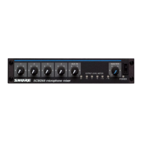
The Shure
SR101 Audio Console may be operated in a
standard 19" (483 mm) audio equipment rack, in a Shure
AlOlA Carrying Case, or custom-mounted in a table- or
desk-type control center. Four rack-mounting screws are
provided with the Console. These screws may also be used
if the Console is to be custom-mounted in a metal-top con-
trol center.
A custom-mounting template is supplied with the Con-
sole. Cutting dimensions and drill hole locations are given,
as are clearances for insertion and ventilation. The
dimen-
 Loading...