ENGLISH
8
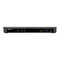
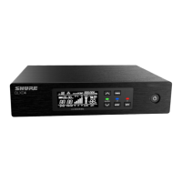
5. Programmable Display: Displays group and channel number, frequency,
squelch level, system name, transmitter battery power level, and display lock on/
off status.
6. + Button: Press this button to scroll display forward.
7. – Button: Press this button to scroll display backward.
8. Audio Output Control: Adjusts receiver output level to match input level require-
ments of a mixer or amplifier. Normally, this control is set fully clockwise.
9. Headphone Monitor Volume Control: Rotate this knob to the right to increase
headphone volume; rotate it to the left to decrease headphone volume.
NOTE: If you are using a Model U4S Receiver, press the Headphone Volume
Control knob to turn the monitor on or off.
If you are using a Model U4D Receiver, press the Headphone Volume Control
knob once to select Receiver 1 or twice to select Receiver 2, depending on which
section you wish to monitor.
10. Headphone Monitor Status: These LEDs glow yellow when the headphone
monitor circuit is turned on or off.
NOTE: The Tone Key feature is present only on the receiver output. As a result,
you may hear an occasional “pop” through the headphones when the transmitter
is turned on or off.
11. Headphone Input Connector: Plug headphones into this 1/4–inch connector to
monitor receiver audio.
12. POWER On/Off Switch: Turns the receiver on and off.
13. Power Input Connector: Accepts power directly from any 90 to 230 VAC, 50/60
Hz power source.
14. Power Output Connector: Provides 90 to 230 VAC, 50/60 Hz power to additional
equipment. It can be used to link multiple receivers or to power the Shure UA840
Antenna Distribution System.
15. Antenna Input Connectors: BNC-type connectors provide connection to the
supplied antennas or to coaxial cable used with a distribution amplifier or remote
antennas.
CAUTION: To avoid damage to equipment, make sure any equipment connected
to the antenna inputs can tolerate 12 VDC power.
16. HIGH Z (Unbalanced) Output Connector: 1/4 inch phone jack provides unbal-
anced auxiliary level (high-impedance) output.
17. Mic/Line Slide Switch: Controls output of balanced XLR connector. It can be set
for microphone or line-level (microphone level = line level – 30 dB).
18. LOW Z (Balanced) Output Connector: XLR connector provides balanced low-
impedance mic level or line-level output.
19. Networking Interface: 25–pin “D” connector provides future electronic interface
to computers and other equipment via accessory interface box.
 Loading...
