- 11 -
Before removing or installing any of these devices including CPU, DIMMs,
Add-On Cards, Cables, please make sure to unplug the onboard power
connector.
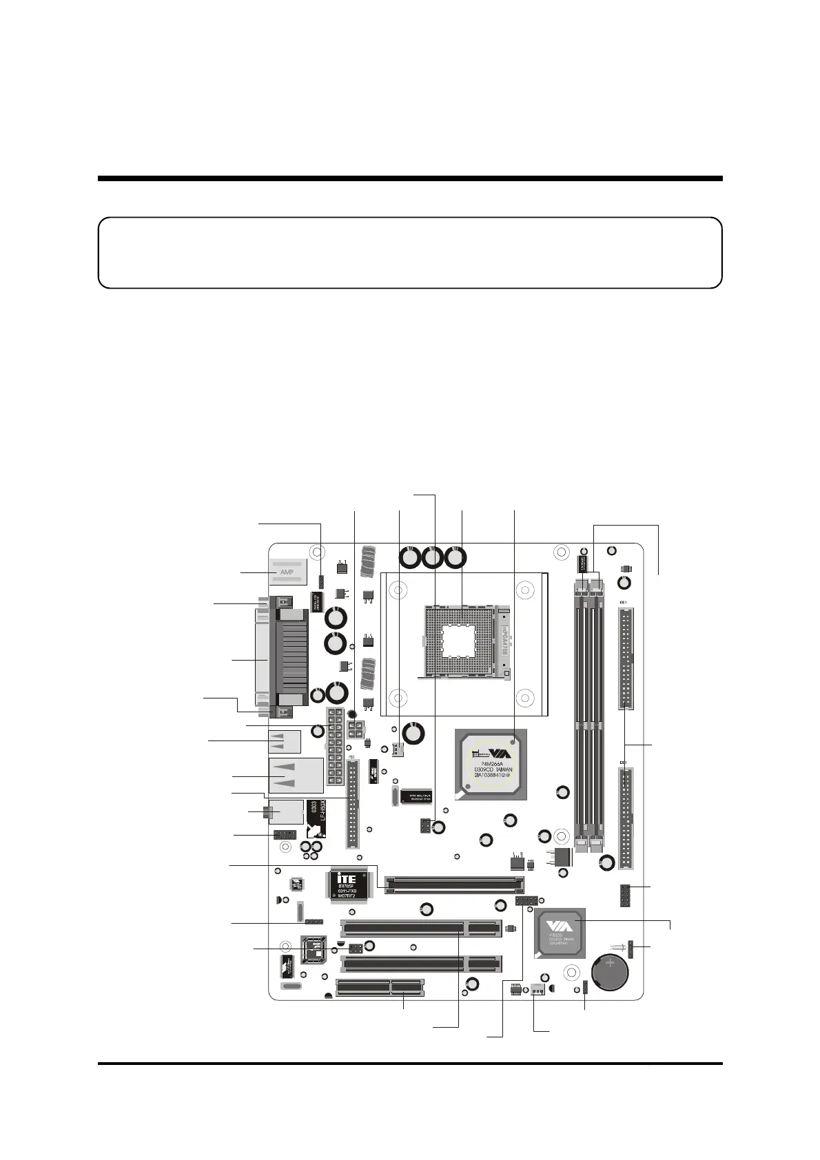
This section outlines how to install and configure your mainboard. Refer to the following
mainboard layout to help you to identify various jumpers, connectors, slots, and ports.
Then follow these steps designed to guide you through a quick and correct installation of
your system.
3.1 Step-by-Step Installation
3 HARDWARE INSTALLATION
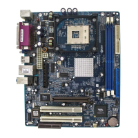
Accessories Of MV43V/MV43VN
PS2-KBMS1
VGA1
USB1
PRINTER
1
PANEL1
1
JP1A1
JP1B1
1
IR
1
JP 2
LINE1
K T S
A
CPU_FAN
Two PCI Slots
One AGP 4x Slot
One CNR Slot
Extended USB header- USB2
Keyboard Power On- JP2
Speaker Connector-SPK1
System FAN
USB & LAN Ports
(MV43VN Only)
Parallel Connector
Serial Port
Connector (COM1)
Panel1 Connector
Panel2 Connector
Serial infrared port-SIR1
Line-Out/Line-In/Mic-In/
Ports
Onboard Audio
Connectors- CD 2
PS/2 Keyboard and
PS/2 Mouse Connectors
CPU FAN
ATX Power Connector
Clear CMOS - JBAT1
Two E-IDE Connectors
USB Ports
Two 184pin DDR DIMM Slots
Socket 478 VIA P4 M266A Chipset
VGA Port
12V ATX Power Connector
Floppy Connector