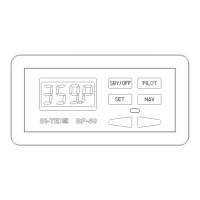
INSTALLATION INSTRUCTIONS
SP-70 and SP-80 AUTOPILOTS
Planning
Caution
Using ordinary electric tools near water is
very dangerous. To minimize the dangers of
electric shock and personal injury, we
recommend using cordless rechargeable
tools or hand tools.
Processor Location
Allow at least a foot or 30 cm of clearance on
either end of the Processor in the space
where it is to be located.
In choosing a location for your SI-TEX
SP-70/SP-80, remember that the Control Unit
Interconnection Cable or Number 1 Cable,
and the cable from the Compass to the
Processor should not be cut or lengthened.
Excess cable may be loosely coiled behind a
panel.
Number 1 Cable from the SP-70 Control Unit
Receptacle to the Processor is 10 feet long
(3.05 metres). Number 1 cable from the SP-
80 Control Unit to Processor is 25 feet long
(7.7 metres).
The cable from the Compass to the
Processor is 40 feet long (12.2 metres).
You will want to have the Control unit near
the steering station you use the most. On
SP-70’s try to position the Receptacle so that
the curly cord will also reach other
convenient locations such as the place
that you use when docking your vessel.
If you are going to use a sealant when
flush mounting the SP-80 Control Head,
be careful to not cover the small square
hole in the middle of the bottom side.
This hole must vent to atmosphere.
Do not mount the Processor near heat
sources, such as heat radiators, or over
engines. If you can, mount the Processor so
that the cooling fins are vertical.
Power Connection
There is a 7.5 foot (2.3 metre) power cable
included with your SI-TEX SP-70/SP-80. We
recommend that you do not lengthen this
cable.
If you must extend the cable:
• Use the smallest extension length
possible.
• Use no less than 10 A.W.G. (6mm
2
)
conductor. Splice and solder the joints.
• The extension must be less than 10 feet
(3 metres).
• Make the joints watertight by using heat-
shrink tubing and silicon, or some other
watertight covering.