Hydraulic Connections For Three-Line Steering Systems
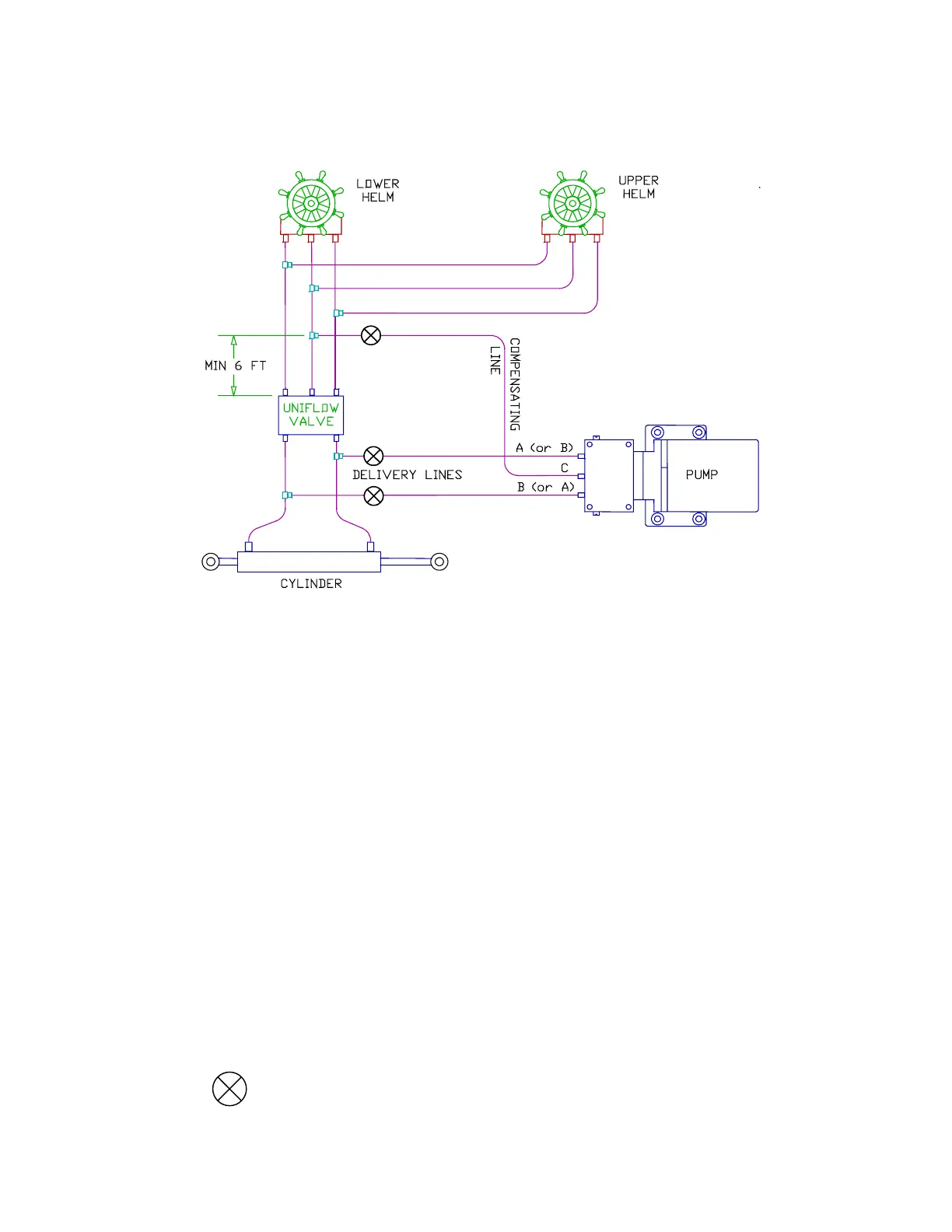
A simple schematic of the pump installation is shown below.
3 Line Steering System Installation
Delivery Lines:
In the above diagram, Ports A and B are the input/output ports of the pump and must be
connected to the steering lines between the steering cylinder and the Uniflow valve. The
simplest method of doing this is to install a tee in each of the cylinder ports of the Uniflow valve
itself and connect to these tees. It does not matter which pump port is connected to which
steering line.
Compensating Line:
Port C is the compensating or bleed line and must be connected to the steering systems’
reservoir. This connection can be made at a helm pump; a remote reservoir (if there is one); the
return line connecting two helm pumps; or the return line between a pump and the Uniflow
valve. If the connection is being made directly to the helm pump, ensure that the bleed line is
connected to the LOWEST bleed port of the pump.
The connection MUST be at least six feet (1.83 m) from the Uniflow valve as shown above. If the
connection is too close to the Uniflow valve, the manual steering system may not work well.
The compensating line MUST have a gradual rise from the pump, to the connection, to the
steering system. This allows air to rise out of the pump, ensuring a constant supply of oil to the
pump.
INSTALLATION OF SHUT-OFF VALVES RECOMMENDED