To
connect the cable, first loosen off the right-hand cap on the SI-TEX Processor Box and remove
the “knock-out” at the top of the cap by using a 9/32 inch (7mm) drill. Once the “knock-out” has
been removed, install the cable gland and the cable. Next connect the individual wires on the
second location cable to the middle terminal strip, paralleling the existing main receptacle wiring
(Cable 1). Test your connections by disconnecting the control unit from the main receptacle and
connecting it to the second station receptacle. For specific information on the installation of the
receptacle and the mounting clip, please refer to page 25 of this manual.
Second Station Kit
Part Number 10080035
The Second Station Kit contains all the items you will require to install a second station outlet for
your autopilot. The kit should contain the following items:
1.
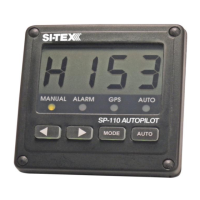
1 only SP-70 Control Head
2.
1 only Mounting Clip for the SP-70 Control Unit.
3. 1 only Cable Gland and Nut.
4.
1 only Receptacle and Cap with 30 foot cable.
5.
1 only Stainless Steel mounting washer.
6.
1 only 6 pin miniature plug.
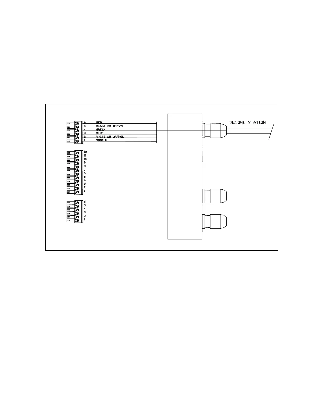
To connect the cable, first loosen off the right-hand cap on the SI-TEX Processor Box and remove
the “knock-out” at the top of the cap by using a 9/32 inch (7mm) drill. Once the “knock-out” has
been removed, install the cable gland and the cable. Next connect the second station wires to the
6 position miniature plug according to the above diagram. Insert the plug into the top position on
the right-hand side. For specific information on the installation of the receptacle and the mounting
clip, please refer to page 25 of this manual.
J8
J9
J7
Right-hand side showing optional second station connections