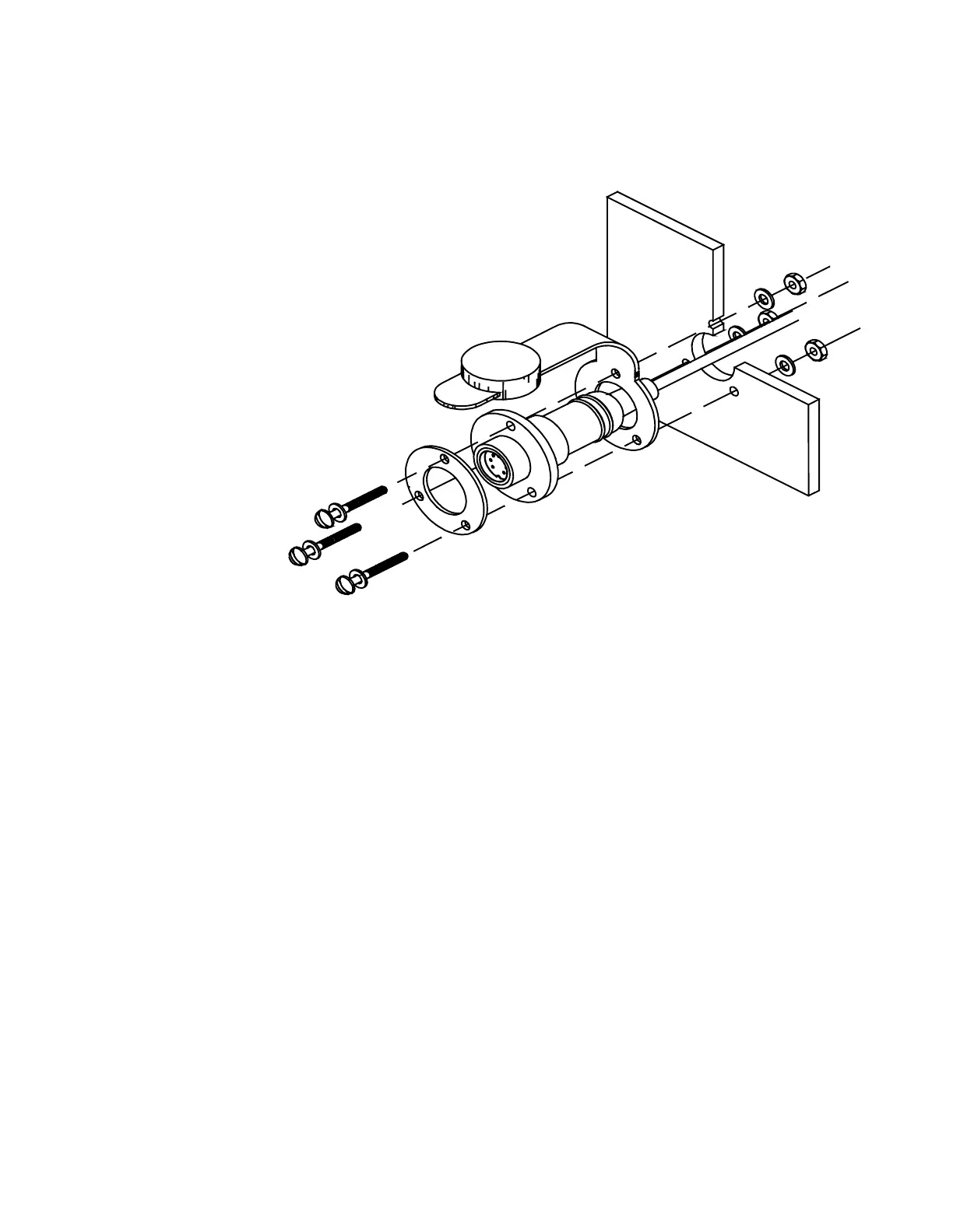
SP-70 Receptacle Installation
The Receptacle is attached to the Number 1 cable. The diagram to the right shows the Receptacle
mounted in a panel.
Mount the receptacle
near your normal
steering position.
The curly cord on the
Control Unit lets you
move about 5 feet
away from the
Receptacle.
A stainless steel ring
is placed between
the bolt heads and
the receptacle
flange. Do not
attempt to seal the
receptacle by over-
tightening the bolts
as the ring will
def
orm t
he
receptacle and
interfere with plug
insertion. A proper
caulking compound
or sealant should be used instead. The three bolts should only be tightened enough to compress
the lock-washers, no more. As the plug has a tight seal, and insertion into the receptacle may be
stiff, a lubricant has been included in your package.
Hole sizes:
Hole for receptacle: 0.825 inches or 21 mm in diameter.
Use the barrel of the Receptacle to mark holes for the flange.
Holes in the flange are for a number 6 (3mm) screw. You may wish to vary this size depending
upon the panel material.
Clip Installation
The Clip is used for mounting the Control Unit. The Clip is mounted with two number 10 (5mm)
screws or bolts.
The usual mounting location is on the dashboard within easy reach when you are steering your
vessel.
Cable 1 Receptacle Installation