13. INTERNAL SENSOR CALIBRATION
Fig.9a
The internal sensor must be calibrated in the following cases:
• the machine displays the message E 4 (sensor calibration not performed) even after having calibrated the external sensor (if present);
- the MBE32F main board has been replaced, or board reset diagnostic test “t5” has been performed.
• the swinging unit has been replaced;
• it was necessary to disassemble the internal sensor due to the diameter sensor replacement.
The procedure for calibrating the internal sensor is as follows:
• Access the service environment and, turning the unit, position it to encoder position notch 200;
• Remaining on this notch, hold down the Enter button (with the cursor on the “spin counter” icon) for approx. 5 seconds. The graphic regarding
the calibration of the internal sensor will appear on the monitor.
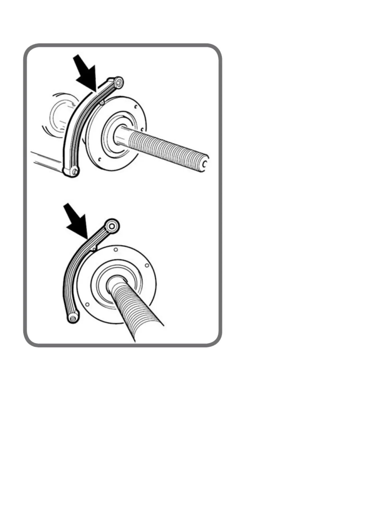
• Move the lever of the internal sensor so it rests against the swinging unit bell as shown in figure 9a;
• Press "Enter" to calibrate the diameter;
• Move the lever of the internal sensor so it rests against the swinging unit flange as shown in figure 9b;