Fig.17e
Check the following if the clamping system does not work and no errors are displayed when the clamping system pedal is pressed:
- check that NO micro-switch (Normally Open) is connected correctly and that the micro-switch is working correctly (A fig.17f). Undo
the nut (B fig.17f) to access the micro-switch;
- the micro-switch cable;
- the electric connections on the MBUGRF card.
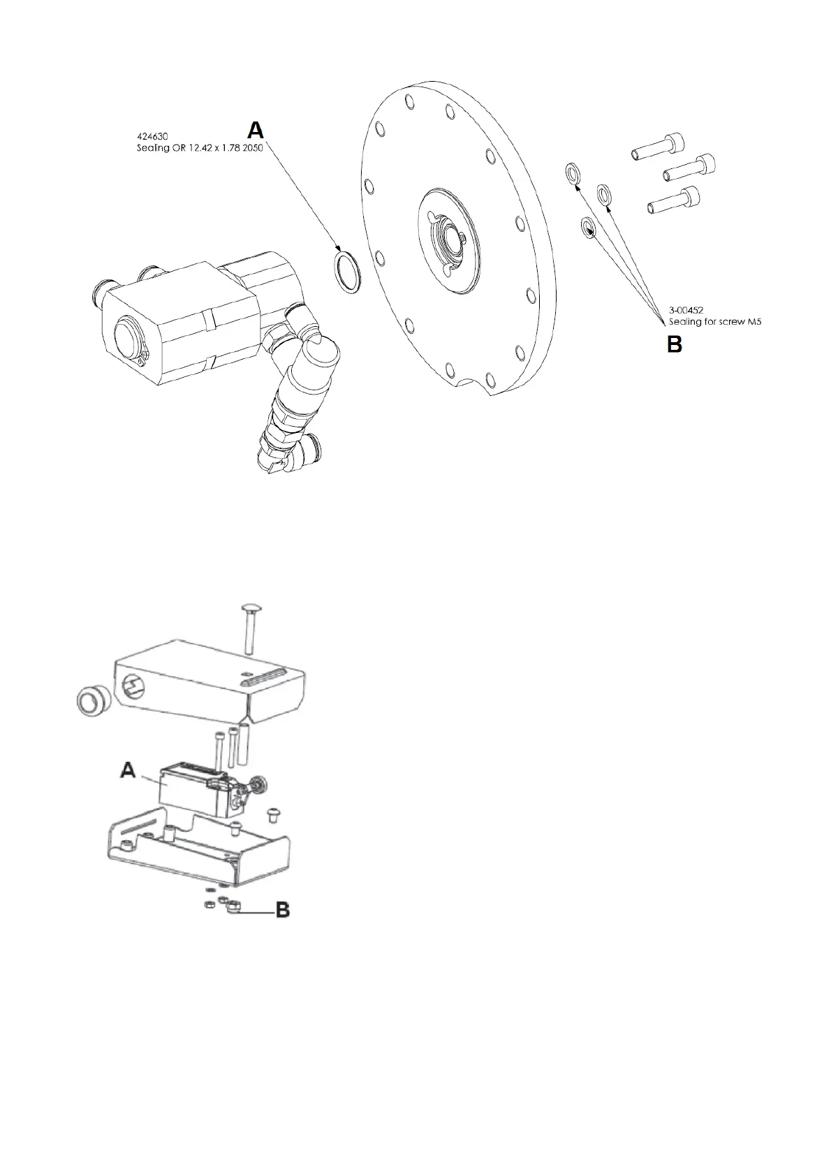
Fig.17f
If necessary, modify the pneumatic circuit PL following these instructions inside the PL ASSISTANCE KIT cod. 5-107159:
- Remove the weight cover
- Remove the solenoid valve inside the machine by means of the two fixing screws
- Remove the pilot valve VBU 1/8 (A, Fig.16) and replace it with the silencer (A1, Fig.16) mounted on the pilot valve VBU 1/8 same
- Remove the connector B of figure 16 and then connect the pipe (C, Fig.16) directly into the connection on the solenoid valve (D, FIg.16).
Insert the ROUND INSERT ROUND PLUG DP-SP D 14.3 H 8.7 cod. 437686 on the back side of the body
- Remove the fitting E (Fig.16) and replace it with the RACCPN-D-G1 / 8G-T6 fitting code. 3-00461
- The modified implant is visible in figure 17g