Mounting
24 © SICK AG • Subject to change without notice • 8014868/YIF1/2020-10-19
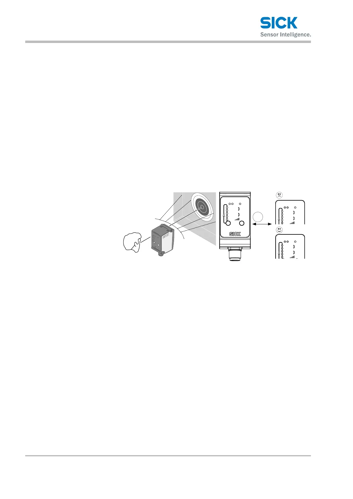
5. Perform ne adjustment. Align the distance sensor such that the
highest possible alignment quality is indicated. The alignment quality is
indicated as follows:
• using the vertically arranged LEDs Q1 near to slow … fast: The great-
er the number of that LEDs light up, the higher the alignment quality.
• using the LEDs Q1 and Q2: The faster both LEDs ash, the higher
the alignment quality. Slow ashing at approx. 1 Hz corresponds to
poor alignment quality (no reective tape). Rapid ashing at approx.
15 Hz corresponds to high alignment quality (highest reective
level).
6. In order to leave alignment mode, either press the set pushbutton
longer than 5 seconds or wait 5 minutes without pushing the pushbut-
tons.
7. Remove the small reective tape for alignment from the object.
8. For DL35 and DR35 variants, attach a large reective tape for perform-
ing the measurement.
Q1 Q2
Q1 near
Q1 far
Q2 near
Q2 far
ObSB
select
set
run
ObSB
fastslow
set
>5s
Q1 Q2
Q1 near
Q1 far
Q2 near
Q2 far
ObSB
run
ObSB
fastslow
Q1 Q2
Q1 near
Q1 far
Q2 near
Q2 far
ObSB
run
ObSB
fastslow
1 Hz
15 Hz
Fig. 7: Aligning infrared light models, entering alignment mode
 Loading...