25
8015675/1EEU/2021-12| SICK O P E R A T I N G I N S T R U C TI O N S | Flow-X
Subject to change without notice
INSTALLATION 4
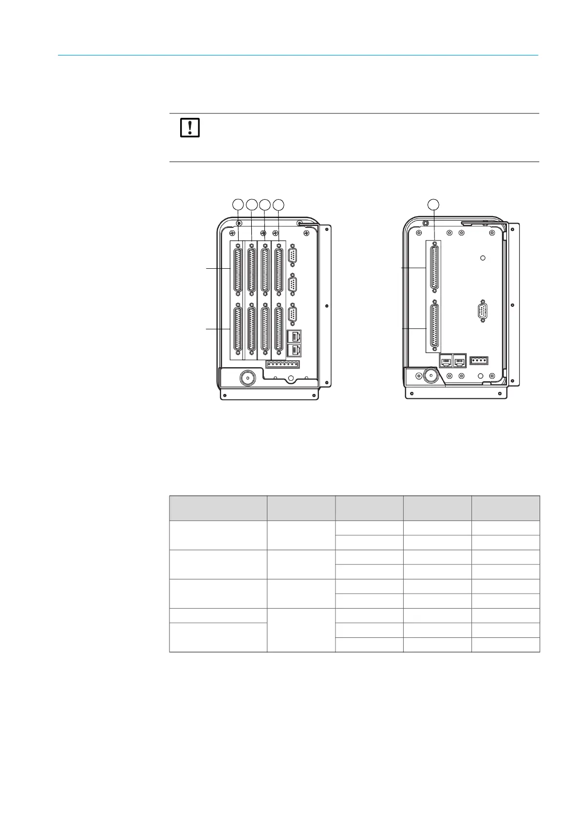
The exact position and type of the relevant connections can be found in the following Tables
and Figures.
Fig. 19: Connection ports Flow-X/P (left) and Flow-X/C (right)
Note:
These Operating Instructions describe the installation of a single measuring section.
Use the connectors of the corresponding measuring section according to the following
Figures when several measuring sections are installed.
D-sub A
D-sub B
1
2
3
4
1 Measuring section 1
2 Measuring section 2
3 Measuring section 3
4 Measuring section 4
1
D-sub A
D-sub B
Connected
device
Terminal ID Plug connection Pin
Serial Com Port 1 Gas flow meter
TRx+ X1A 1
TRx- X1A 2
Analog/HART Input 1
Pressure
transmitter
+ X1A 32
- X1A 33
Analog/HART Input 2
Temperature
transmitter
+ X1A 34
- X1A 35
24 V out
Pressure or
temperature
transmitter
X1A 1
0 V common
X1A 2
X1A 4
Table 6: 37-pin connection port (Flow-X/P and Flow-X/C)