5.4.11 Connecting Flexi-Line system
Important information
WARNING
L
imited safety due to buffering elements
The target safety-related level may not be achieved in the event of non-compliance.
►
Do not use any buffering elements in a Flexi Line system, such as CAN bridges,
CAN repeaters or CAN-capable optical photoelectric sensors.
►
Do not use any other components except Flexi Line stations in a Flexi Link system.
NOTICE
O
vervoltage at the Flexi Line inputs
The device may be damaged if this is not observed.
►
Observe the maximum permissible voltage at the Flexi Line inputs of ±30V (to
terminal A2=GND).
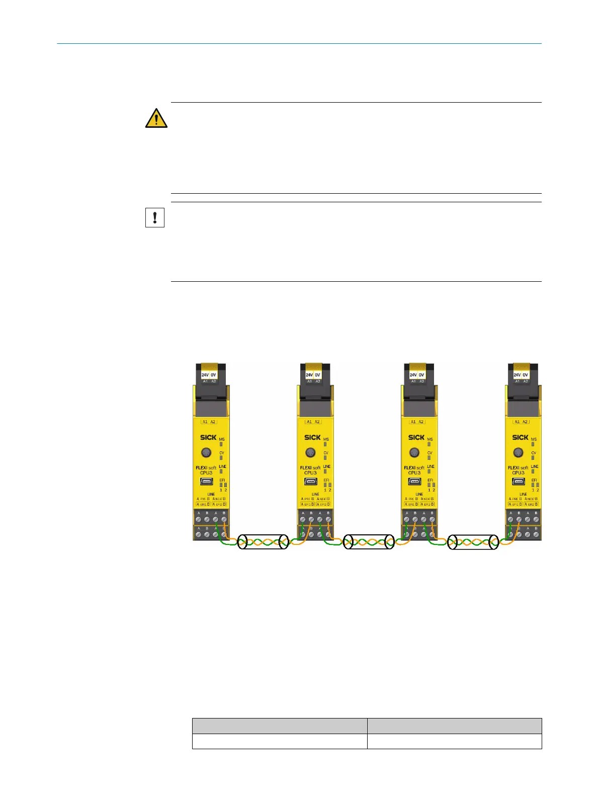
Approach
1. Connect the NEXT connection of each station to the PRE connection of the next
station.
2. Connect the identically named terminals with one another, i.e. A with A and B with
B.
Figure 60: Connection of a Flexi-Line system
3. Connect not used cables to the functional earth (FE) at both ends.
Complementary information
C
onnection:
•
No external terminator is required for the Flexi Line connections on the main
module.
•
Stub cables or star-shaped wiring are not allowed.
•
The maximum permissible total length between two Flexi-Line stations is 1,000m.
Flexi-Line cables
•
Flexi-Line stations can be connected using CAN cables (shielded, twisted pair).
Table 79: Possible lengths of cable and types for Flexi Line connections
Length of cable Cable type
Up to 40m 2 × 0.22mm² (AWG 23)
5 ELECTRICAL INSTALLATION
100
O P E R A T I N G I N S T R U C T I O N S | Flexi Soft Modular Safety Controller 8012478/1IG6/2023-02-24 | SICK
Subject to change without notice