3.3.1.1 Illumination unit
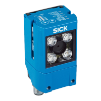
Figure 2: Illumination unit (integrated illumination unit)
1
4 x LED (2 x left / 2 x right)
2
Feedback LED (e.g. for Good Read) = 1 x green LED
3
Aiming laser for alignment, can be deactivated = 2 x red laser LEDs
NOTE
Do not look into the viewing window of the device in order to avoid dazzling from the
integrated illumination unit.
3.3.2 Display and operating elements
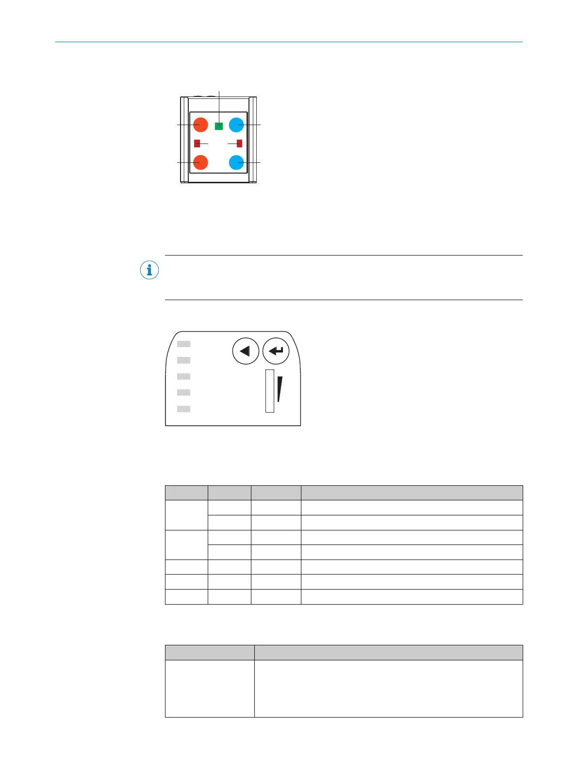
Ready
Read Diagn
Result
TeachIn
LED
Auto-Setup
Data
Autofocus
LNK TX
Userdefined
300
200
100
70
40
100
0
[mm]
[%]
O
O
O
O
O
Figure 3: LED status displays and bar graph on the top of the device
Status displays in read mode
Table 4: First display level
Display LED Color Status
Ready Lights up Green Device is ready
Lights up Red Hardware or software error
Result Lights up Green Read operation successful
Lights up Red Read operation unsuccessful
LED Lights up Green Read mode: illumination on, internal reading interval open
Data Lights up Yellow Data output via host interface
LNK TX Flashing Green Data traffic via Ethernet
Functions
Table 5: Function overview
Function Description
Read Diagn (read diag‐
nosis)
Percentage analysis: The device records a series of images and uses
the current reading performance settings to decode them. With the
0 ... 100% bar graph, the device shows the read rate of the last 10%
(90% to 100%).
The bar graph display is activated in standard read mode.
PRODUCT DESCRIPTION 3
8024289//2019-08-15 | SICK O P E R A T I N G I N S T R U C T I O N S | GLS6
15
Subject to change without notice