Table 22: Signal assignment of adapter cable with open end
Pin Signal Function Wire color
1 GND Ground Blue
2 V
S
Supply voltage Brown
3 CAN L CAN bus (IN/OUT) Green
4 CAN H CAN bus (IN/OUT) White
5 TD+ (RS-422/485), host Host interface (sender+) Pink
6 TD– (RS-422/485), host
TxD (RS-232), host
Host interface (sender-) Yellow
7 TxD (RS-232), Aux AUX interface (sender) Black
8 RxD (RS-232), Aux AUX interface (receiver) Gray
9 SensGND Digital input ground White-black
10 Sensor 1 Digital input 1 Violet
11 RD+ (RS-422/485), host Host interface (receiver+) Gray-pink
12 RD– (RS-422/485), host
RxD (RS-232), host
Host interface (receiver–) Red-blue
13 Result 1 Digital output 1 White-green
14 Result 2 Digital output 2 Brown-green
15 Sensor 2 Digital input 2 White-yellow
16 N. c. – Yellow-brown
17 N. c. – White-gray
13.3.2 “Power/SerialData/CAN/I/O” connection to customer-specific connection equipment or control
cabinet
Adapter cable suitable for drag chain, deep-freeze compatible
Part no. 2075220 (5 m), shielded, suitable for drag chain, deep-freeze compatible, suit‐
able for 2 A
Permitted currents for ambient temperature +40 °C:
•
Contact 1 (blue) and contact 2 (brown): 2 A
•
All other contacts: 1.5 A
Ambient temperature range:
For mobile installation: –25 °C to +80 °C, for fixed installation: –40 °C to +85 °C
...
ð
3
1
7
2
6
5
4
8
13
14
17
15
9
10
12
16
11
1 2
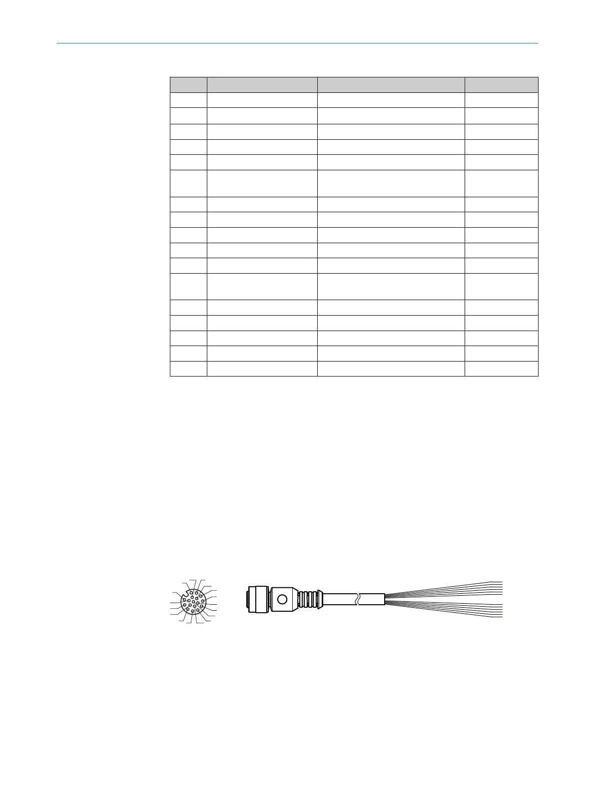
Figure 22: Adapter cable, part no. 2075220 (5 m)
1
Female connector, M12, 17-pin, A-coded (view from front)
2
Illustration may differ
13 ANNEX
56
O P E R A T I N G I N S T R U C T I O N S | GLS6 8024289//2019-08-15 | SICK
Subject to change without notice