6.3 Connection diagrams
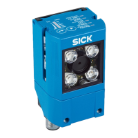
6.3.1 Connection principle for service operation
This operating mode is recommended for initial commissioning of the device.
NOTE
The USB interface of the device is used in industrial environments only as a service
interface for temporary use (e.g. for configuration, troubleshooting). Permanent use in
real operation of the system as a host interface is not intended.
GLS6
Configuration
Image display
Diagnostics
SOPASSOPAS
"Power/Serial Data/
CAN/I/O"
(Aux 1, Host 1)
V
S
1
PC
"Ethernet" (Aux 2,
image transfer) 4
"USB" (Aux 1, for
temporary use only) 2
Cable 3
EthernetEthernet
USBUSB
6
Cable 5
Cable 7
1
Supply voltage V
S
(V
S
= U
V
)
2
USB, alternative to Ethernet AUX port
USB for temporary use only as a servicing interface
3
Adapter cable (male connector, USB, Micro-B type/male connector, USB, type A)
4
Ethernet AUX port alternative to USB
5
Adapter cable (male connector, M12, 4-pin, D-coded/male connector, RJ-45, 8-pin)
6
Configuration with SOPAS ET, image display or reading diagnostics
7
Cable with open end
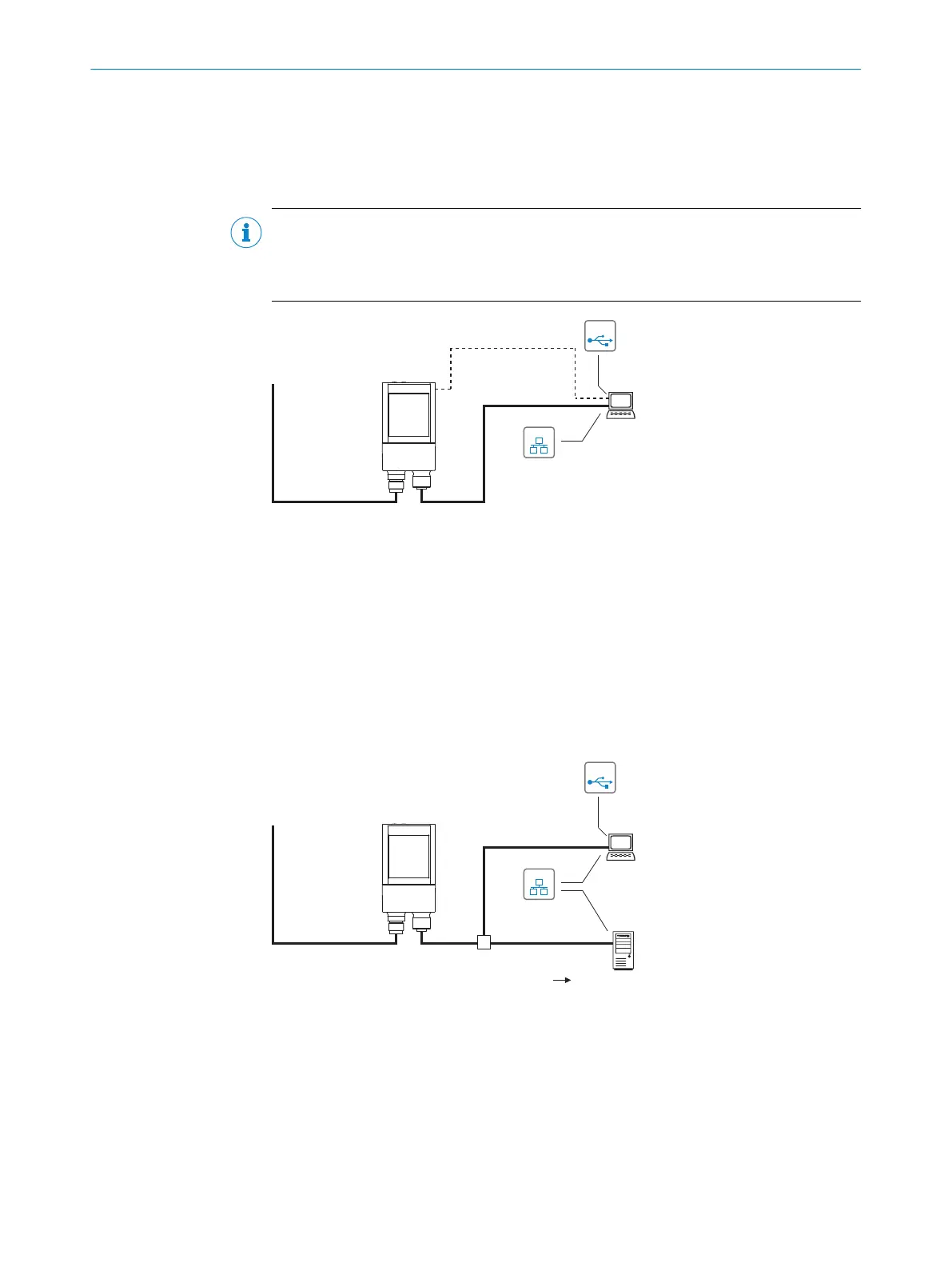
6.3.2 Connection principle for read mode
"Ethernet"
(Host 2)
GLS6
Image display
SOPASSOPAS
"Power/Serial Data/
CAN/I/O"
(Aux 1, Host 1)
V
S
1
HOST
PC
Further data
processing
"Ethernet" (Aux 2,
image transfer) 2
EthernetEthernet
USBUSB
Cable 6
3
5
Reading result 4
1
Supply voltage V
S
(V
S
= U
V
)
2
Ethernet AUX port (image transmission)
3
Image display
4
Read result
5
Data further processing
6
Cable with open end
6 ELECTRICAL INSTALLATION
32
O P E R A T I N G I N S T R U C T I O N S | GLS6 8024289//2019-08-15 | SICK
Subject to change without notice