–y
+y
–x +x
1
2
3
4
5
α = 270° α = 90°
α = 180°
α = 0°
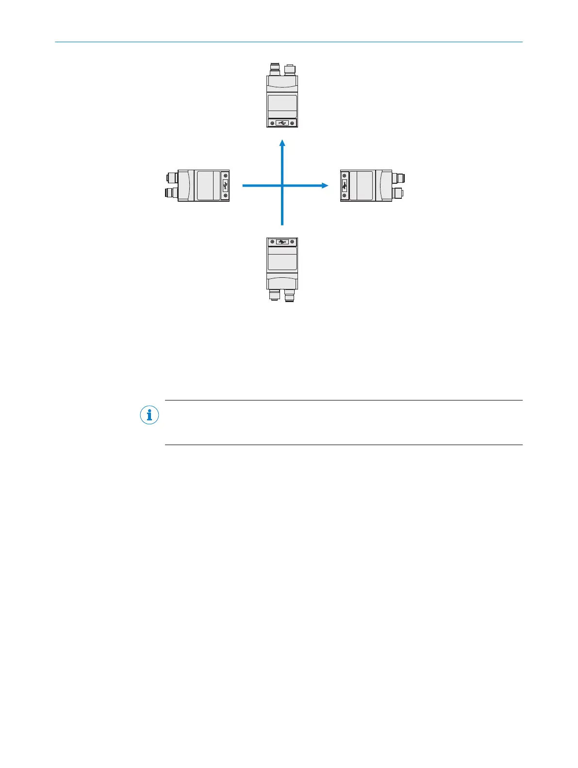
Figure 11: Mounting angle α
1
Coordinate system of the field of view
2
Angle α = 0° (default value), direction of motion according to + y
3
Angle α = 90°, direction of motion according to - x
4
Angle α = 180°, direction of motion according to - y
5
Angle α = 270°, direction of motion according to + x
NOTE
If problems with reflections occur, use a polarizing filter (part number: 2088228), see
see "Accessories", page 52.
5.4 Mounting the device
Perform one of the following steps:
•
Mount the device on a bracket supplied by the customer using M5 screws. Screw
the screws no more than 5 mm into the tapped blind holes or sliding nuts.
•
Attach the optional SICK bracket that has been ordered separately (e.g. mounting
angle, part number 2042902) to the device using the two sliding nuts.
5 MOUNTING
26
O P E R A T I N G I N S T R U C T I O N S | GLS6 8024289//2019-08-15 | SICK
Subject to change without notice