6.4 Pin assignments of electrical connections
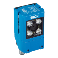
“Power/Serial data/CAN/I/O” connection
3
1
7
2
6
5
4
8
13
14
17
15
9
10
12
16
11
Figure 16: Male connector, M12, 17-pin, A-coded
Table 7: Pin assignment of the “Power/Serial data/CAN/I/O” connection
Pin Signal Function
1 GND Ground
2 V
S
Supply voltage
3 CAN L CAN bus (IN/OUT)
4 CAN H CAN bus (IN/OUT)
5 TD+ (RS-422/485), host Host interface (sender+)
6 TD– (RS-422/485), host
TxD (RS-232), host
Host interface (sender-)
7 TxD (RS-232), Aux AUX interface (sender)
8 RxD (RS-232), Aux AUX interface (receiver)
9 SensGND Digital input ground
10 Sensor 1 Digital input 1
11 RD+ (RS-422/485), host Host interface (receiver+)
12 RD– (RS-422/485), host
RxD (RS-232), host
Host interface (receiver–)
13 Result 1 Digital output 1
14 Result 2 Digital output 2
15 Sensor 2 Digital input 2
16 Result 3 Digital output 3
17 Result 4 Digital output 4
– – Shield
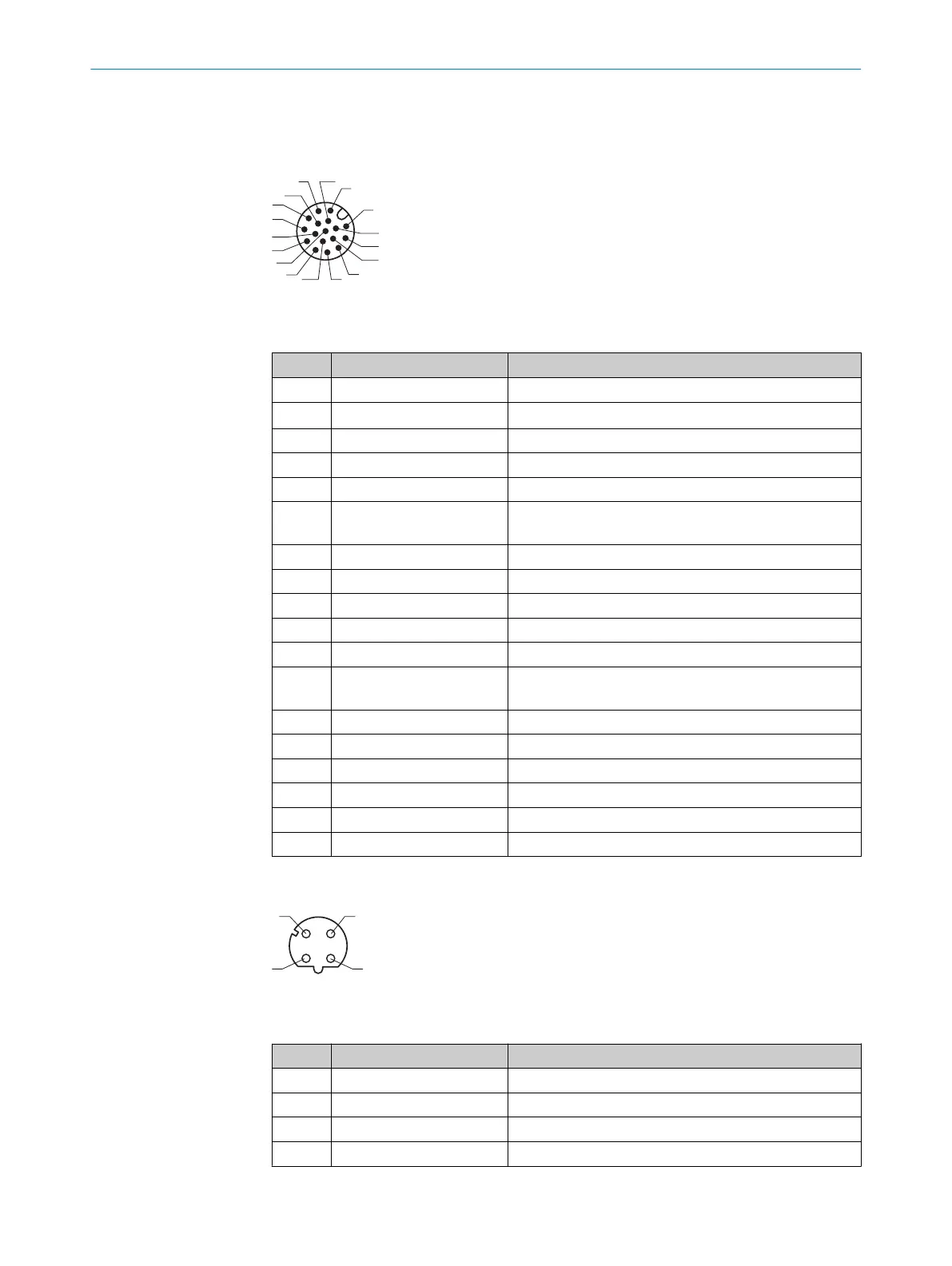
“Ethernet” connection
Figure 17: M12 female connector, 4-pin, D-coded
Table 8: Pin assignment of the “Ethernet” connection
Pin Signal Function
1 TD+ Sender+
2 RD+ Receiver+
3 TD– Sender–
4 RD– Receiver–
ELECTRICAL INSTALLATION 6
8024289//2019-08-15 | SICK O P E R A T I N G I N S T R U C T I O N S | GLS6
33
Subject to change without notice