3 Mounting
3.1 Scope of delivery
•
Cont
rast sensor in the version ordered
•
Quickstart
•
Safety notes
3.2 Mounting requirements
•
Typic
al space requirement for the device, see type-specific dimensional drawing,
see "Technical data", page 23.
•
Comply with technical data, such as the permitted ambient conditions for opera‐
tion of the device (e.g., temperature range, EMC interference emissions, ground
potential).
•
To prevent condensation, avoid exposing the device to rapid changes in tempera‐
ture.
•
Protect the device from direct sunlight.
•
The device must only be mounted using the pairs of mounting threads/fixing holes
provided for this purpose.
•
Shock and vibration-free mounting.
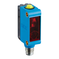
3.3 Mounting the device
Figure 1: KTML
1. Install the sensor via the fixing hole so that the light spot enters the mark longitu‐
dinally and t
he test object has the least possible vertical and horizontal move‐
ment. Note the sensing distance while doing so.
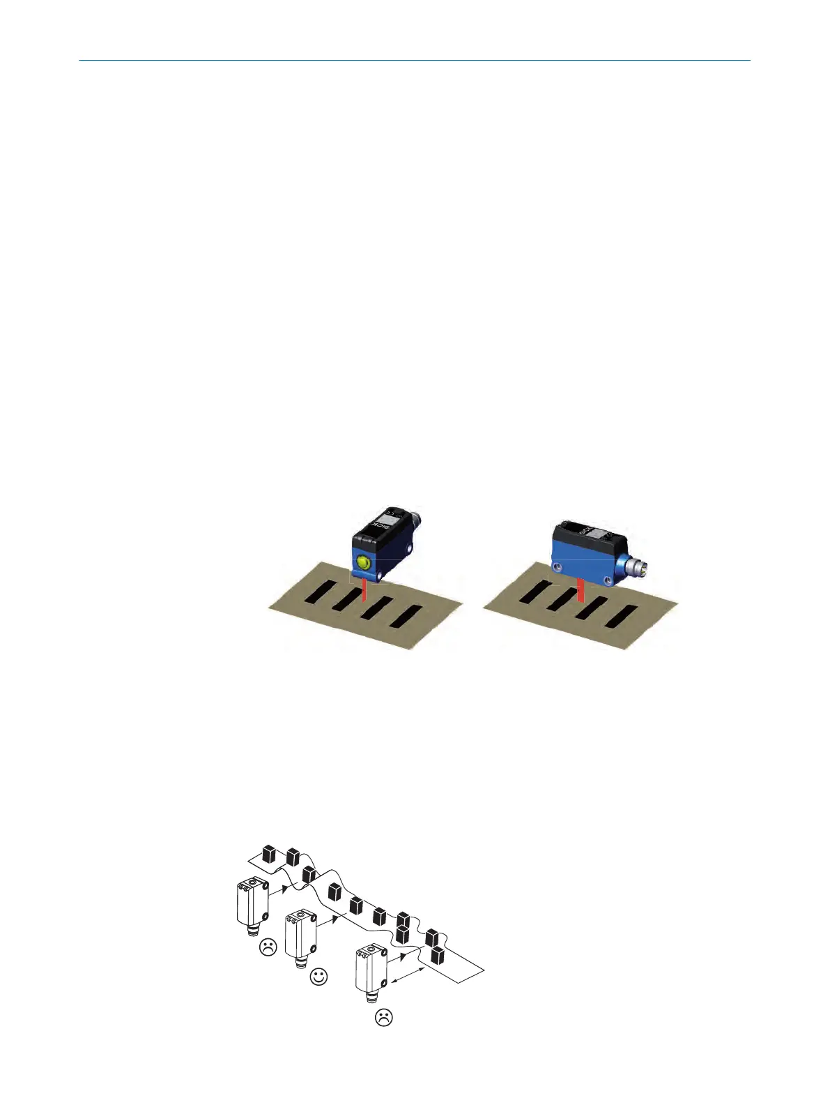
2. Compensate for the vertical and horizontal movement of the test object by marks
of suitable lengths.
3. Ensure that any sensor movement does not affect the sensing distance.
To secure a stable detection when having high gloss material a tilt angle of 10°-15°
might be necessary.
3 MOUNTING
10
O P E R A T I N G I N S T R U C T I O N | KTML 8025181/09.01.2020 | SICK
Subject to change without notice