5.2 Pin assignment of the connections
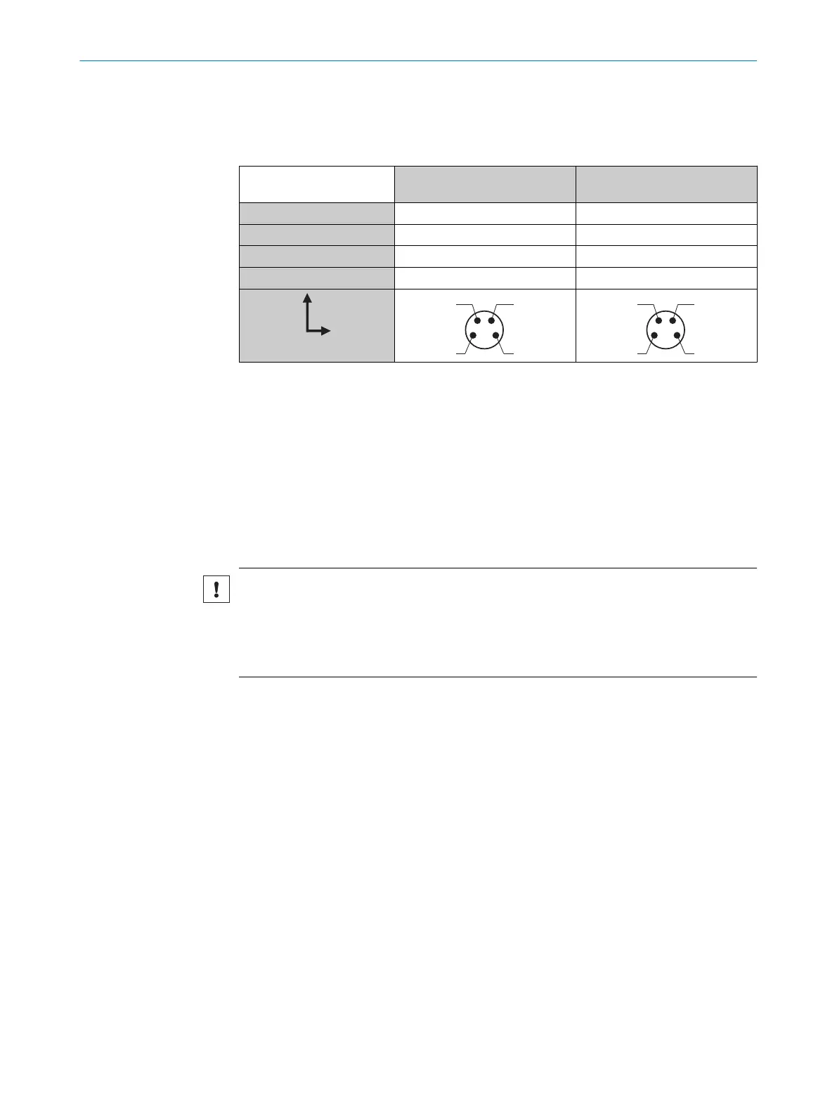
Overview of pin assignment
T
able 1
: DC
KTM- Lxxx181P
Lxxx182P
Lxxx7A1P
Lxxx742P
1 = BN + (L+) + (L+)
2 = WH ET Q
3 = BU - (M) - (M)
4 = BK Q C/Q
Legend
L+ = supply v
oltage
ET = external teach-in
M = ground
Q = switching output
C = Communication
5.3 Connecting the supply voltage
NOTICE
Risk of damage to the device!
The device can become damaged if it is connected to a voltage supply that is already
switched on.
•
Only connect the device when the supply cable is de-energized.
The device must be connected to a power supply unit with the following properties:
•
Suppl
y voltage DC 10.8 V – 28.8 V (SELV/PELV as per currently valid standards)
•
Electricity source with at least 3 W power
To ensure protection against short-circuits/overload in the customer’s supply cables,
the wire cross-sections used must be appropriately selected and protected.
5 ELE
CTRICAL INSTALLATION
14
O P E R A T I N G I N S T R U C T I O N | KTML 8025181/09.01.2020 | SICK
Subject to change without notice