Operating Instructions
LMS1xx Laser Measurement Sensors
Mounting
8012471/ZN27/2017-06-09 © SICK AG · Germany · All rights reserved · Subject to change without notice 59
Chapter 5
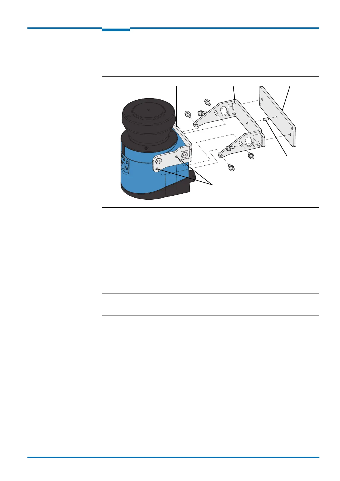
5.3.3 Mounting with mounting kit 2 and 3
With the aid of mounting kits 2 and 3 (only in conjunction with mounting kit 1a or 1b) you
can align the LMS1xx in two planes. The maximum adjustment angle is ±11° in both planes.
Fig. 33: Mounting with mounting kit 2 (part no. 2039302) and kit 3 (part no. 2039303)
1. Mount mounting kit 1a or 1b to the LMS1xx.
2. Mount the mounting kit 3 on the mounting surface.
3. Fit the centring pin (4 mm) in the central hole on mounting bracket 3.
4. Fit mounting kit 2 to mounting kit 3 and mount it using two fixing screws M4 × 10.
5. Then mount the LMS1xx on mounting kit 2 with the aid of the threaded holes in
mounting kit 1a.
6. Adjust the LMS1xx longitudinally and transversely and then tighten the six fixing screws
on the mounting kits.
Important During mounting, please observe the dimensional drawings (see section 10.3.3
“Dimensional drawings mounting kits” on page 101).
Centring pin
Mounting kit 1a Mounting kit 2 Mounting kit 3
Threaded holes M4