Operating Instructions
LMS1xx Laser Measurement Sensors
Electrical installation
8012471/ZN27/2017-06-09 © SICK AG · Germany · All rights reserved · Subject to change without notice 69
Chapter 6
6.2.2 Connections of the LMS11x and LMS15x
“Power” connection
Destruction of the device!
Connecting the sensor incorrectly can lead to the destruction of the device.
Connect the supply voltage for the sensor correctly. Reverse connection is not
permitted.
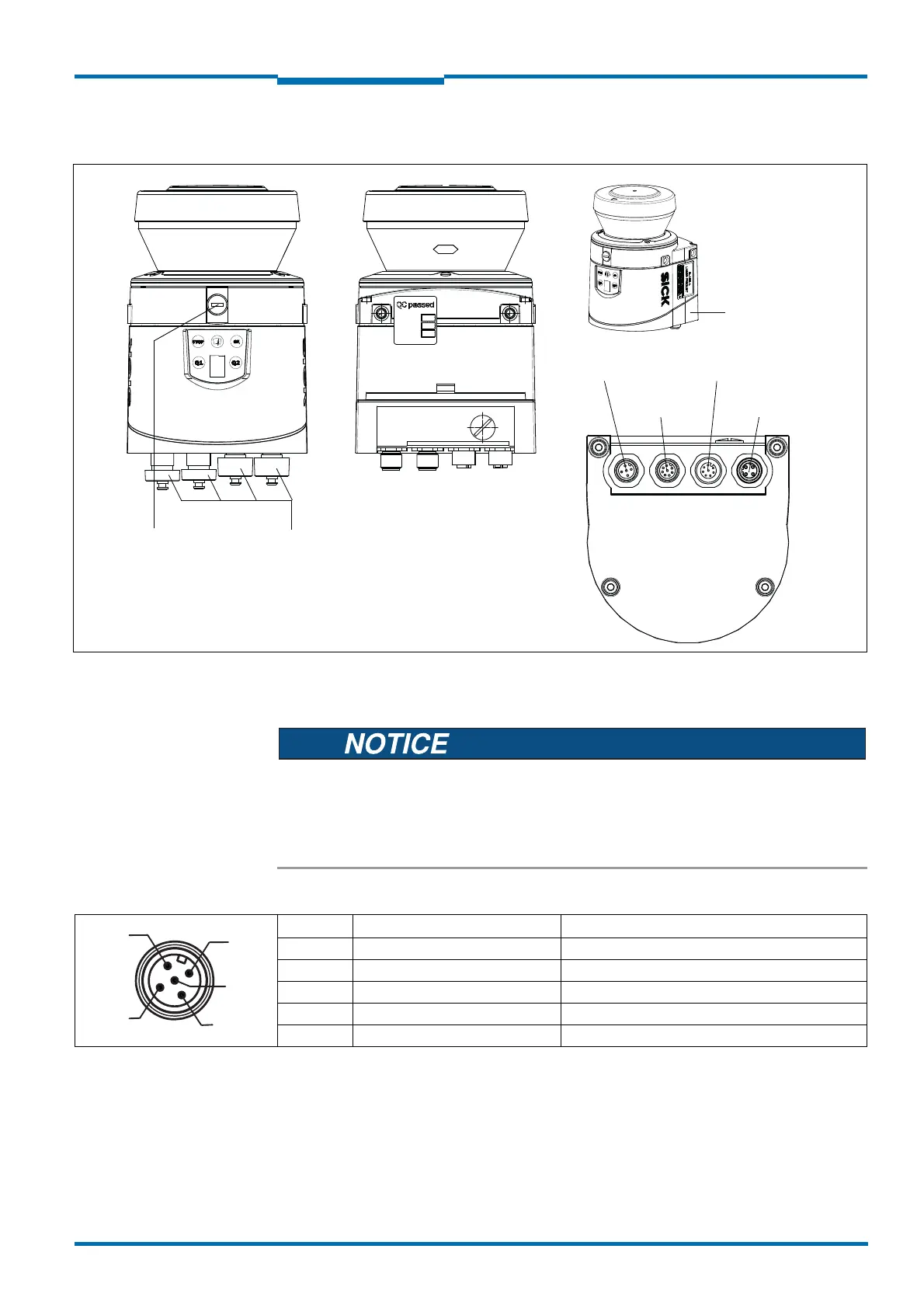
Fig. 45: LMS11x/LMS15x: Position of the electrical connections
“AUX” connection
(behind cover)
System connector
“Ethernet”
connection
“Power”
connection
“I/0”
connection
2)
“Data”
connection
1)
Protection caps
and plugs (IP 67)
1) LMS1xx Security Outdoor and VdS Semi Outdoor:
“Inputs” connection with differing signal assignment
2) LMS1xx Security Outdoor and VdS Semi Outdoor:
“Alarm” connection with differing signal assignment
Pin Signal Function
1 V
S
Power Supply Sensor
2 V
S
heat. Power Supply Heating
3 GND Ground Sensor
4 Reserved Do not use!
5 GND heat. Ground Heating
Tab. 22: LMS11x/LMS15x: Pin assignment of the “Power” connection (5-pin M12 male connector, A-coded)
 Loading...


