Figure 21: Sequence of segment output. The segment i is from the time t
i-1
to t
i
3.4.8.4 Data preparation
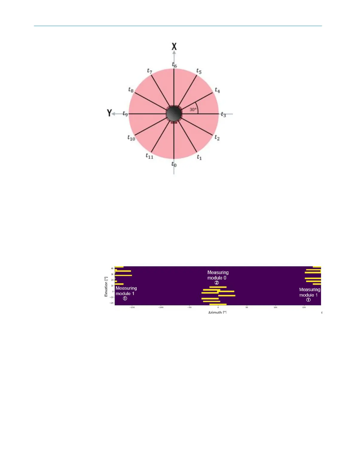
The yellow bars in the following figures indicate the number of measuring points
depending on the resolution over a range of 30°.
Raw data (RAW)
Because the device has two measuring modules that point in opposite directions and
the sender/receiver units on each measuring module have an azimuth offset, the
azimuth range that is recorded for each scan layer in a segment is different.
Figure 22: Example azimuth and elevation angles for the data recorded within a segment (RAW)
1
Measuring module 1
2
Measuring module 0
Rectified data (RECTIFIED)
The data for each scan layer recorded by a measuring module are rearranged so their
start angles match (apart from a small deviation that is attributable to the different
sending times of the transmitter elements of a measuring module). This rearrangement
affects the latency, however, and leads to a delay of at least one time interval.
3 PRODUCT DESCRIPTION
28
O P E R A T I N G I N S T R U C T I O N S | multiScan136 8027119/0000/2022-11 | SICK
Subject to change without notice