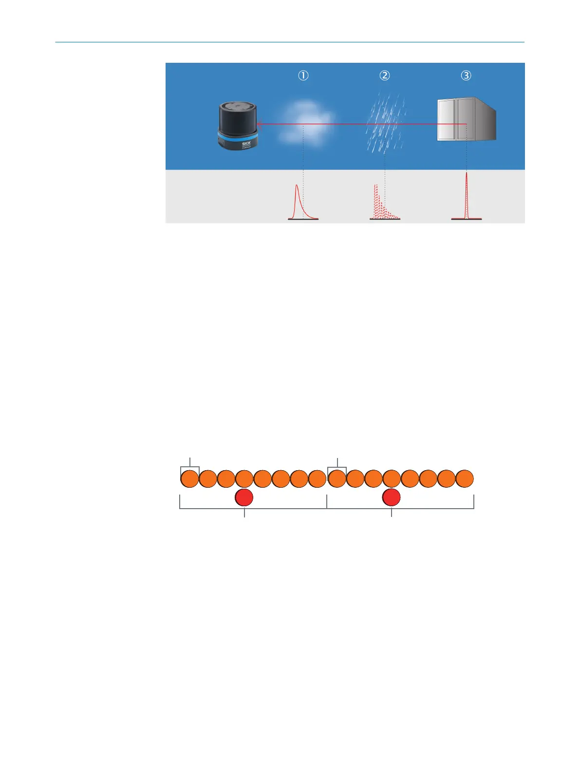
Figure 10: Multi-echo analysis: example industrial application for building management.
1
Fog
2
Rain
3
Measuring object
3.4.4 Direction measurement
The laser beams are emitted using internally rotating sender-receiver units (SRUs) and
scan the surroundings orbitally. The received measured values are assigned to the
associated angular cut and thus to the direction.
The rate at which a laser beam is emitted in a counterclockwise direction differs
depending on the scan layer and device variant. The two high-resolution scan layers
(scan layer 6 and 14 see figure 5, page 15) send a set of 24pulses over an angular
range of 0.125° every 0.125°. A measured value is then derived from the received
signals for these pulses. All other scan layers send 24pulses over an angular range
of 0.125° every 1° of rotation. This gives an angular resolution of 0.125° for the
high-resolution scan layers and 1° for every other scan layer.
1°
0,125°
24x
1
2
24x 24x 24x 24x 24x 24x
24x 24x
1°
0,125°
24x
24x
24x
24x
24x 24x 24x 24x 24x
Figure 11: Schematic representation of the sequence of events based on the example of one
high-resolution scan layer and one scan layer
1
High-resolution scan layer
2
Scan layer
3.4.5 Multi-layer technology
The multi-layer technology of the device uses 16scan layers at different vertical angles
to compensate for pitch angle, for example when the device is attached to a vehicle.
This enables the device to reliably detect an object even, for example, when the vehicle
accelerates or brakes.
3 PRODUCT DESCRIPTION
18
O P E R A T I N G I N S T R U C T I O N S | multiScan136 8027119/0000/2022-11 | SICK
Subject to change without notice