obj
min
Minimum object angle [°]
α
spot
Beam spot size [°], here 0.3°
α
meas
Measuring interval [°], see table 5, page 30
α
res
Angular resolution [°], horizontal 0.125°, vertical 0°
Table 5: Typical minimum object size [mm] as a function of distance and angular resolution
Angular resolu‐
tion [α
res
]
Horizontal
0.125°
(red high-resolu‐
tion scan layer
see figure 24 )
Horizontal 1.0°
(orange scan
layer see
figure 24)
Vertical 2.5°
(between red and
orange scan layer
see figure 24)
Vertical 5.0°
(between two
orange scan lay‐
ers see figure 24)
Distance [mm]
100 13 13 13 13
200 13 13 13 19
500 13 13 26 47
1000 13 25 51 95
2000 19 50 102 190
3000 29 75 153 285
5000 48 124 255 475
10000 96 249 511 950
15000 144 373 766 1425
20000 192 498 1022 1899
25000 240 622 1277 2374
30000 288 746 1533 2849
NOTE
For reliable measurement, in particular when using the device to output measured val‐
ues, the laser needs to hit the object with multiple beams. An object should therefore
be larger than the minimum object size.
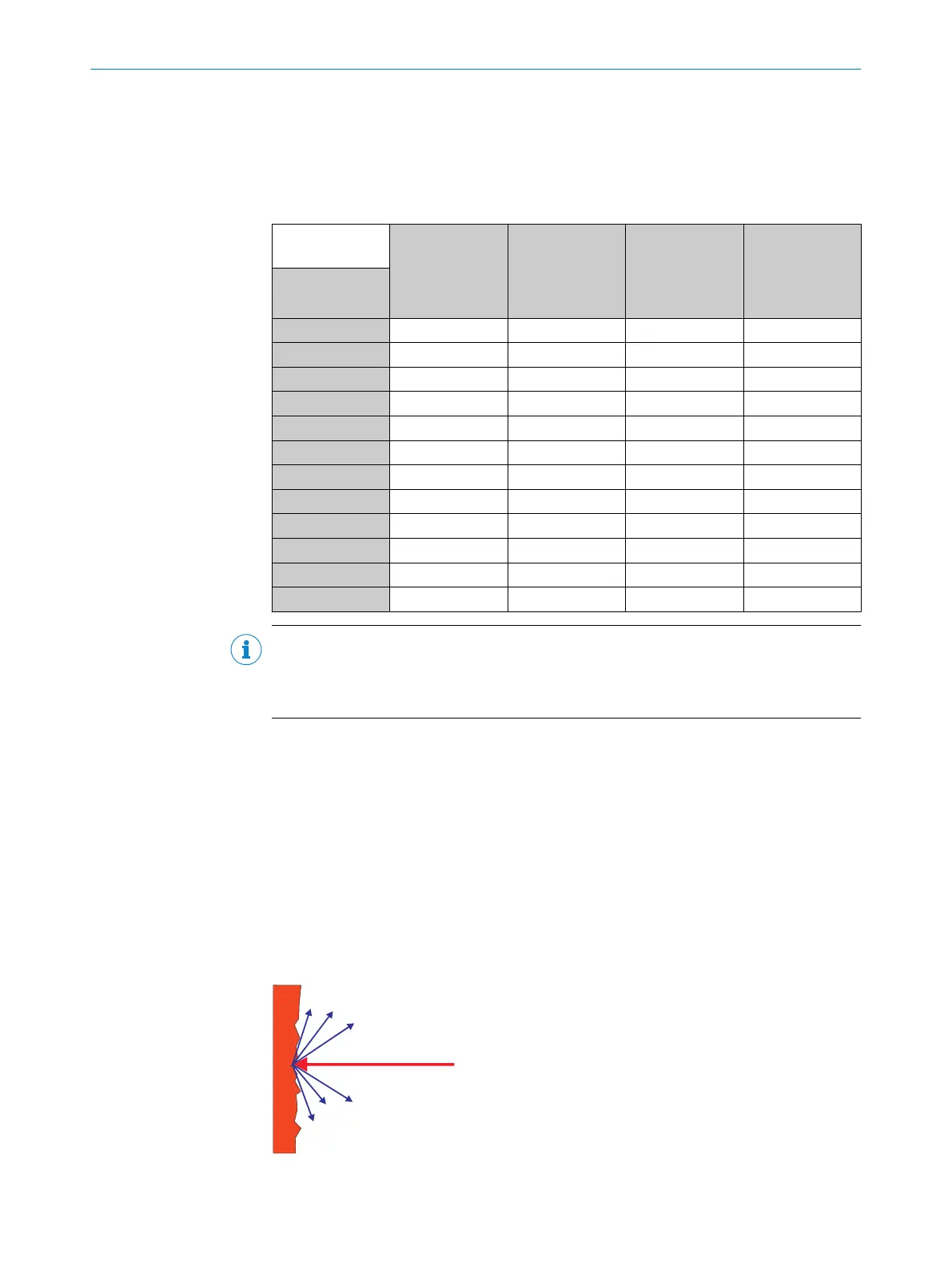
3.4.10 Impact of object surfaces on the measurement
Reflection
Most surfaces produce a diffuse reflection of the laser beam in all directions. The
structure (smooth or rough), shape (flat or curved), and color (light or dark) of the
surface determine how well the laser beam is reflected.
On very rough surfaces, a large proportion of the energy is lost due to absorption.
Curved surfaces produce a higher diffusion. Dark surfaces reflect the laser beam worse
than light ones (brilliant white plaster reflects approx. 100% of the light, while black
foam rubber reflects approx. 2.4%). The aforementioned surface characteristics can
reduce the scanning range of the device, in particular for surfaces with low remission
values.
Figure 25: Reflection of light on the surface of the object
3 PRODUCT DESCRIPTION
30
O P E R A T I N G I N S T R U C T I O N S | multiScan136 8027119/0000/2022-11 | SICK
Subject to change without notice