Figura: E
35.3 Sistema eletrônico
Operação no modo I/O padrão:
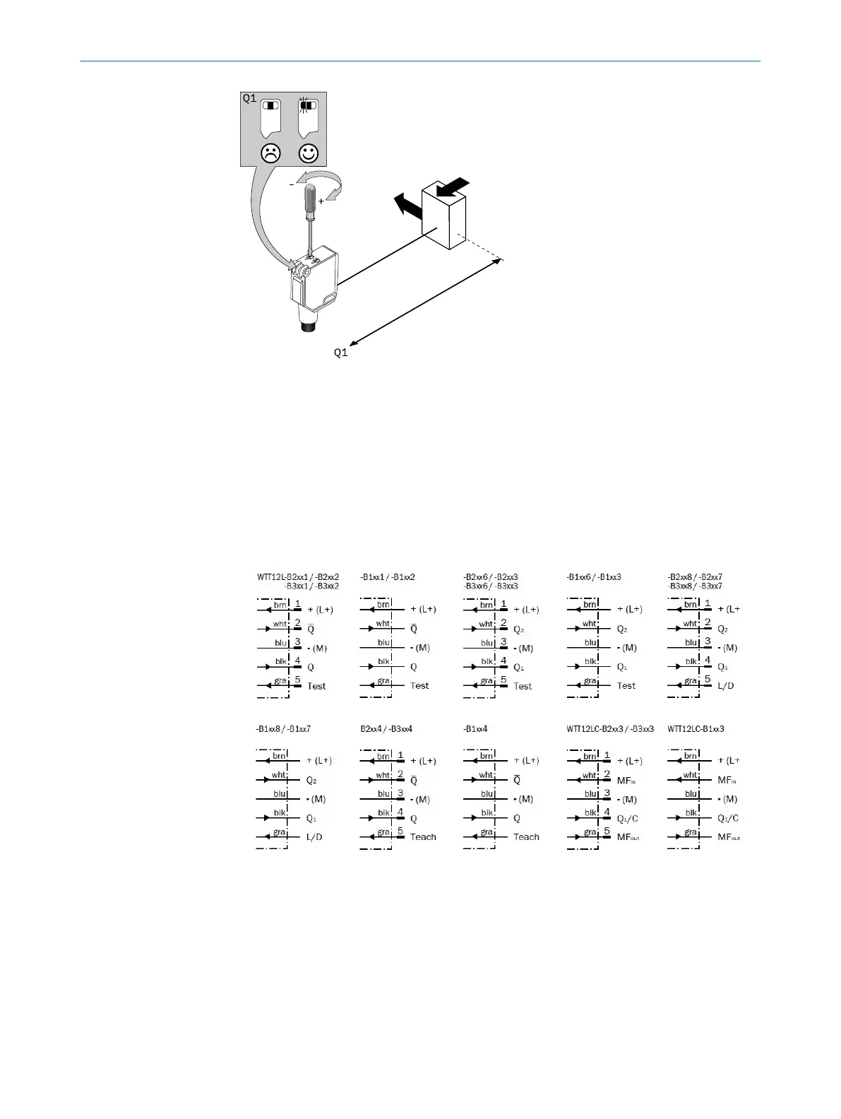
A conexão dos sensores deve ser realizada em estado desenergizado (U
V
= 0 V). Con‐
forme o tipo de conexão, devem ser observadas as informações contidas nos gráficos
[cp. B]:
– Conector: Pin-out
– Cabo: Cor dos fios
Figura 21: B
Instalar ou ligar a alimentação de tensão (U
V
> 0 V) somente após a conclusão de
todas as conexões elétricas. O indicador LED verde está aceso no sensor.
Operação no modo IO-Link: conectar o dispositivo a um mestre IO-Link adequado e
integrá-lo ao mestre ou ao comando através de IODD/bloco funcional. O indicador LED
verde está intermitente no sensor. O download da IODD e do bloco funcional pode ser
efetuado em www.sick.com com o número de encomenda.
COLOCAÇÃO EM OPERAÇÃO
35
8018110.1BVZ / 2021-05-18 | SICK
Subject to change without notice
55

 Loading...