Figura: E
43.3 Electrónica
Funcionamiento en modo E/S estándar:
Los sensores deben conectarse sin tensión (U
V
= 0 V). Debe tenerse en cuenta la
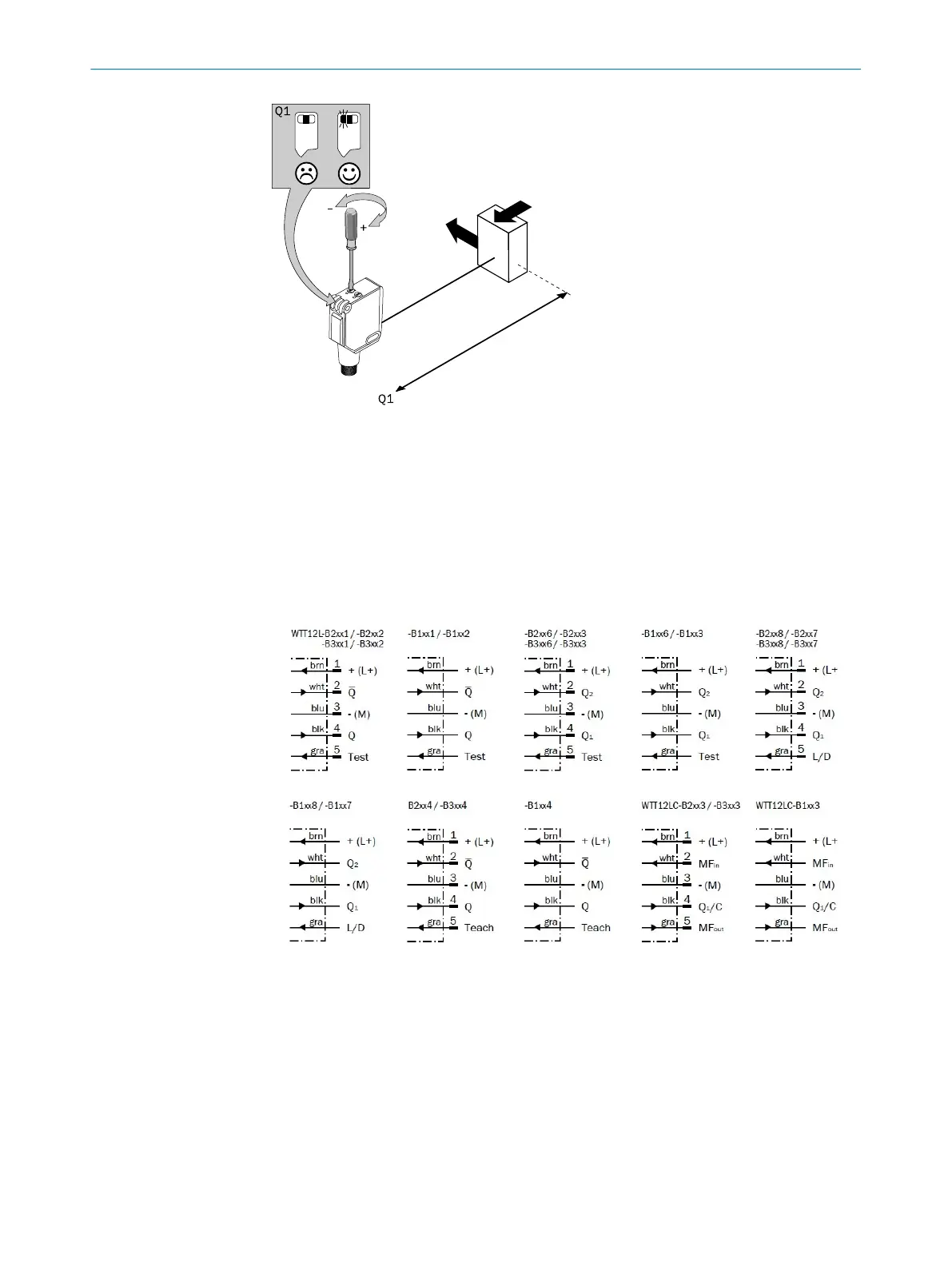
información de las figuras [B] en función de cada tipo de conexión:
– Conexión de enchufes: asignación de terminales
– Cable: color del hilo
Figura 26: B
No aplicar o conectar la fuente de alimentación (U
V
> 0 V) hasta que no se hayan
finalizado todas las conexiones eléctricas. En el sensor se ilumina el LED indicador
verde.
Funcionamiento en modo IO-Link: conectar el dispositivo al maestro IO-Link adecuado
e integrarlo en el maestro o en el control con la ayuda de la hoja de datos IODD y
el bloque de funciones. En el sensor parpadea el LED indicador verde. La hoja de
datos IODD y el bloque de funciones se encuentran disponibles para su descarga en la
página web www.sick.com indicando el número de pedido.
PUESTA EN MARCHA
43
8018110.1BVZ / 2021-05-18 | SICK
Subject to change without notice
67

 Loading...