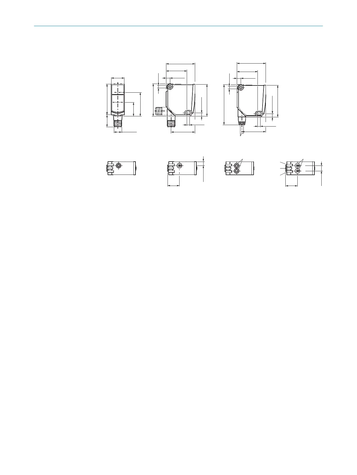
2.2 Dimensional drawings
WTT12L-X2xxx -X1xxx / -X3xxx
-Xxxx2 / -Xxxx4 -Xxxx1
-Xxxx3 / -Xxxx7 -Xxxx6 / -Xxxx8
1
2
7
6
7
9
8
3
4
5
20
(0.79)
44.2 (1.74)
31.9 (1.26)
6 (0.24)
44.2 (1.74)
31.9 (1.26)
6 (0.24)
Ø 4.2
(0.17)
Ø 4.2
(0.17)
49.6 (1.95)
5.1 (0.2)
48.7 (1.92)
61.6 (2.43)
47 (1.85)18.5 (0.73)
36.3 (1.43)
21.1
(0.83)
M12x1
36.5 (1.44)
4 (0.16)
5.1 (0.2)
48.7 (1.92)
4 (0.16)
36.5 (1.44)
6 (0.24)
8 (0.31)
18.3
(0.72)
18.3
(0.72)
Figure: Maßzeichnung WTT12L
1
Center of optical axis, sender
2
Center of optical axis, receiver
3
Potentiometer / LED indicator yellow: status of received light
beam
4
Potentiometer / LED Indicators (green): Power on
5
Potentiometer / LED indicator yellow: status of received light
beam
6
Mounting hole D4.2 mm
7
Male connector, M12, 4-pin or cable
8
Potentiometer
9
Single teach-in pushbutton
2.3 Additional functions
Test input: The WTT12L sensor features a test input ("TI" or "Test" on the connection
diagram [B]), which can be used to switch the sender off and therefore check that the
sensor is functioning correctly: If female cable connectors with LED indicators are used,
you must ensure that the TI is assigned accordingly.
There must be an object in the path of the beam (light reception); activate the test input
(see the connection diagram [B], TI 24 V). The send LED is shut down or no object being
detected is simulated. Refer to Graphics C to check the function. If the switching output
fails to behave in accordance with Graphic C, check application conditions. See section
Fault diagnosis.
The sensor can be used in standard I/O mode (SIO) or IO-Link mode (IOL). All auto‐
mation functions and other parameter settings are effective in IO-Link mode and in
standard I/O mode (exception: time stamp). Output of binary switching signals during
standard I/O operation via pin 4/black wire or via pin 5/gray wire.
Information on the IO-Link functions can be found in the enclosed IO-Link photoelectric
sensors operating instructions or downloaded from www.sick.com under the device
order number.
PRODUCT DESCRIPTION 2
8018110.1BVZ / 2021-05-18 | SICK
Subject to change without notice
5

 Loading...