5 Mounting
5.1 Overview of mounting procedure
NOTICE
Damage to device through improper mounting.
Mount the device in an environment corresponding to enclosure rating IP54
(EN 60529), e.g., inside a control cabinet with enclosure rating IP54.
NOTE
The mounting procedure described here for the device meets the requirements for use
in the target system.
Additional or different requirements may become necessary in the laboratory and dur‐
ing preparation, and should be taken into account as necessary, see "Commissioning",
page 23. If you have any questions or anything remains unclear in this regard, please
contact our service team.
•
Mounting the device.
•
Connect the cables.
•
Connecting peripheral devices.
•
Connecting the voltage supply.
5.2 Scope of delivery
•
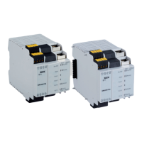
SIM in the version ordered
•
Safety note
•
Optional: ordered accessories
With special variants, where optional extras have been ordered, or owing to the latest
technical changes, the actual scope of delivery may vary from the features and illustra‐
tions shown here.
5.3 Mounting the device
•
Mount the device in accordance with EN 50274.
•
Ensure suitable ESD protective measures during mounting.
•
Implement suitable measures to prevent any foreign bodies from entering the
connector openings or ventilation slots.
•
The module is housed in a 67.5 mm wide housing for standard 35 mm rails in
accordance with EN 60715 (mounting rail).
•
Due to the FLEXBUS+ plug connector integrated into the housing, the total width of
the SIM1000 FXG is 73.5 mm.
•
Install the module in the control cabinet in such a way that the minimum distance
to the control cabinet is adhered to. This distance is 50 mm above and below the
module, and25 mm to the front and back.
•
Mount the module vertically. The ventilation slots must be positioned at the top
and bottom.
•
Mount the module in such a way as to allow vertical air circulation.
5 MOUNTING
14
O P E R A T I N G I N S T R U C T I O N S | SIM1000 FXA, SIM1000 FXG 8023299/1BLK/2021-07-28 | SICK
Subject to change without notice

 Loading...


