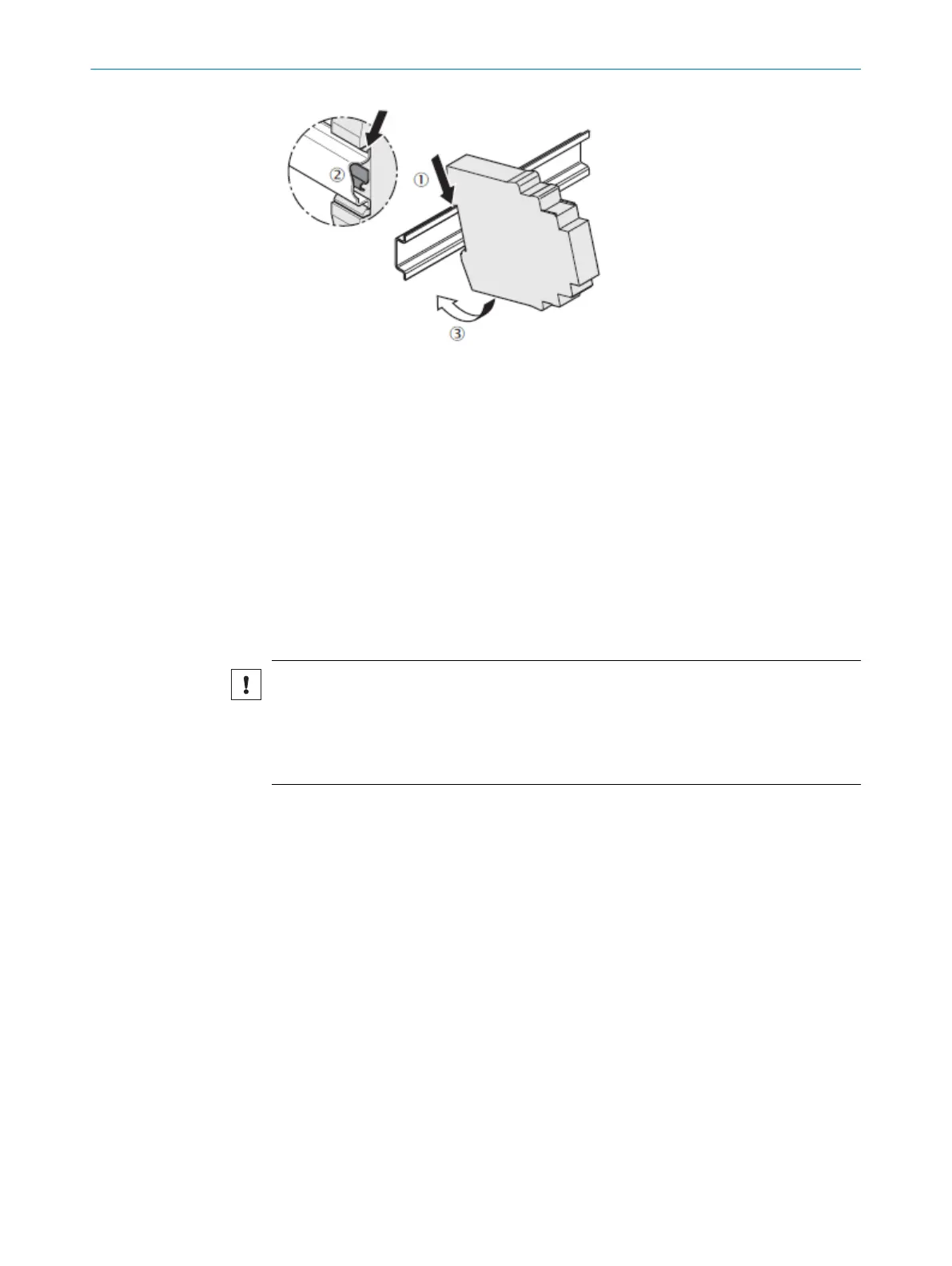
Figure 3: Mounting the device, illustration only
1
Mounting rail
2
Grounding clip
3
Direction of engagement with the mounting rail
1. Make sure that the voltage supply is switched off.
2. Hook the device onto the DIN mounting rail.
3. The grounding clip must sit flush against the mounting rail so that it is secure and
can conduct electricity effectively.
4. Snap the module into place on the mounting rail by applying a slight pressure in
the direction of the arrow.
5. Mount the end pieces on the left and right side of the module.
5.4
Special instructions for mounting the SIM1000 FXG
NOTICE
Improper mounting
The device may be damaged in the event of non-compliance.
■
The SIM1000 FXG is supplied with voltage via the FLEXBUS+ connection.
■
Ensure suitable ESD protective measures during mounting.
Assignment of the modules:
•
In a Flexi Soft system, the FX3-CPUx main module is always located on the far left.
•
Up to two SIM1000 FXG or one SIM1000 FXG and one Flexi Soft gateway can be
used per system. The SIM1000 FXG and the optional Flexi Soft gateway must be
mounted directly to the right of the main module of the Flexi Soft system.
•
All other Flexi Soft expansion modules (z. B. FX3-XTIO, FX3-XTDI or FX3-MOCx)
must be mounted to the right of the SIM1000 FXG and the Flexi Soft gateway. The
expansion modules can be mounted in any order.
•
Any additional relay modules (the UE410-2RO or UE410-4RO) must be mounted to
the right of the expansion modules.
MOUNTING 5
8023299/1BLK/2021-07-28 | SICK O P E R A T I N G I N S T R U C T I O N S | SIM1000 FXA, SIM1000 FXG
15
Subject to change without notice