The device is now in Run mode and ready to use.
Top left value: Upper threshold (digits) of the current or voltage range
(assignment of the displayed value to the current or voltage value
20mA/10V/5V)
Bottom left value: Lower threshold (digits) of the current or voltage
range (assignment of the displayed value to the current or voltage value
4mA/0V/1V)
Right value: Current received light value (digits)
NOTE
The initial menu settings are also shown in a video:
7.3 Setting the sensing range/switching threshold/current or voltage range/teach-in
Setting the sensing range or defining the switching point or assigning received light values (digits) to the current or
voltage range can be done manually or using various teach-in modes that can be selected in the teach-in menu.
7.3.1 Binary switching channel Q1
Manual setting the switching points:
The switching point or switchings points can be set manually.
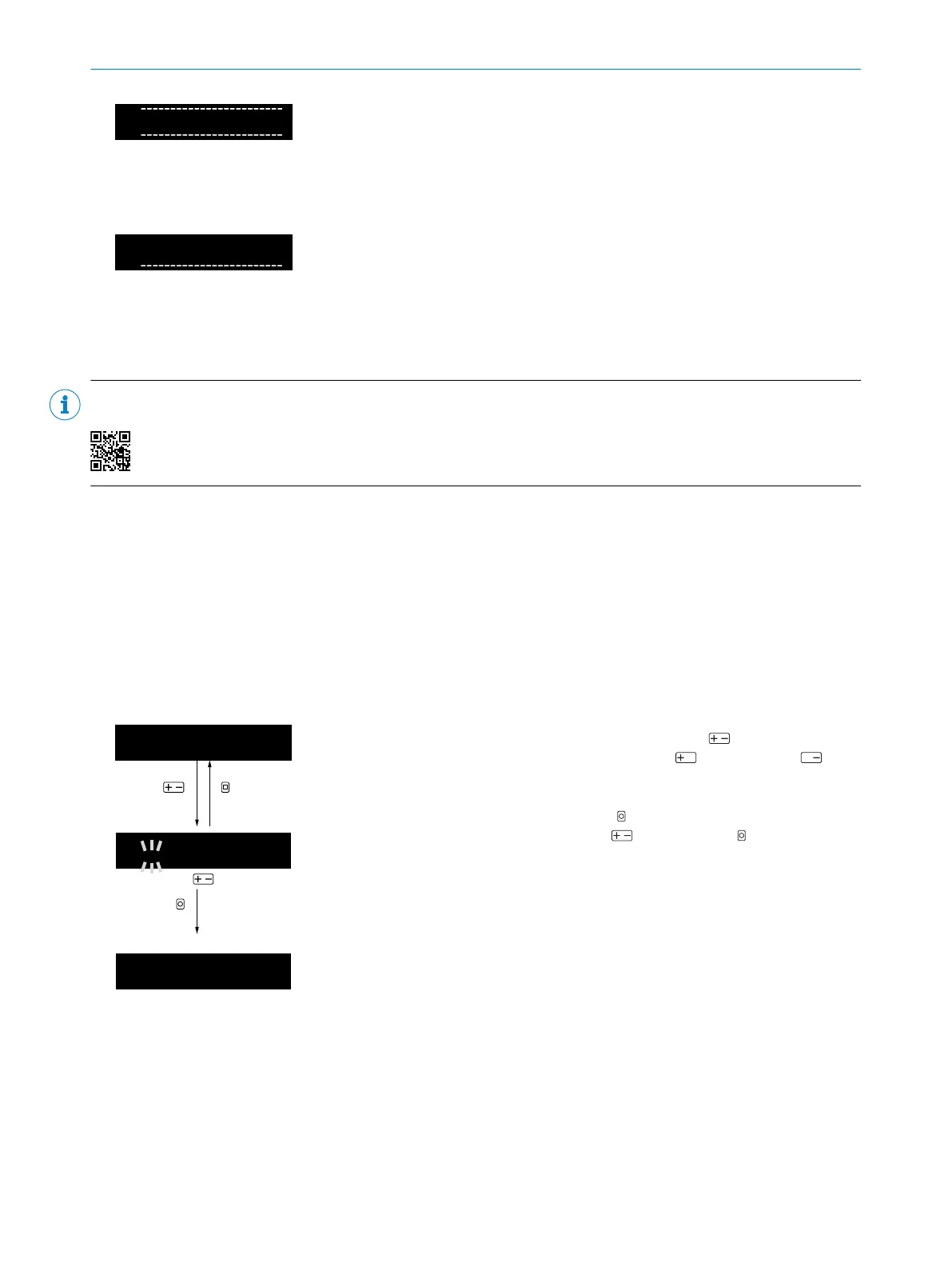
Table 5: Manually setting the switching points
1
A
|
1000
100
OK
Adjustment with
Manually setting the switching point/switching points
Activate manual setting of the switching point using (switching
point flashes). Adjust the switching point using (increase) and
(decrease).
In modes (zone teach-in, window teach-in) with two switching points – SP1
and SP2 – after confirming SP1 using OK, the display changes to the
setting of SP2. Adjust SP2 also using . Confirm using .
After confirmation (or after 30seconds without button operation), the
display returns to run mode.
2-point teach-in:
The 2-point teach-in sets the switching point SP1 to the average value between the received light values of two
teach-in points TP1 and TP2. You can teach in the teach-in point with object or without object first.
7
COMMISSIONING
18
O P E R A T I N G I N S T R U C T I O N S | WLL80 Analog 8027947 /2022-12-14 | SICK
Subject to change without notice