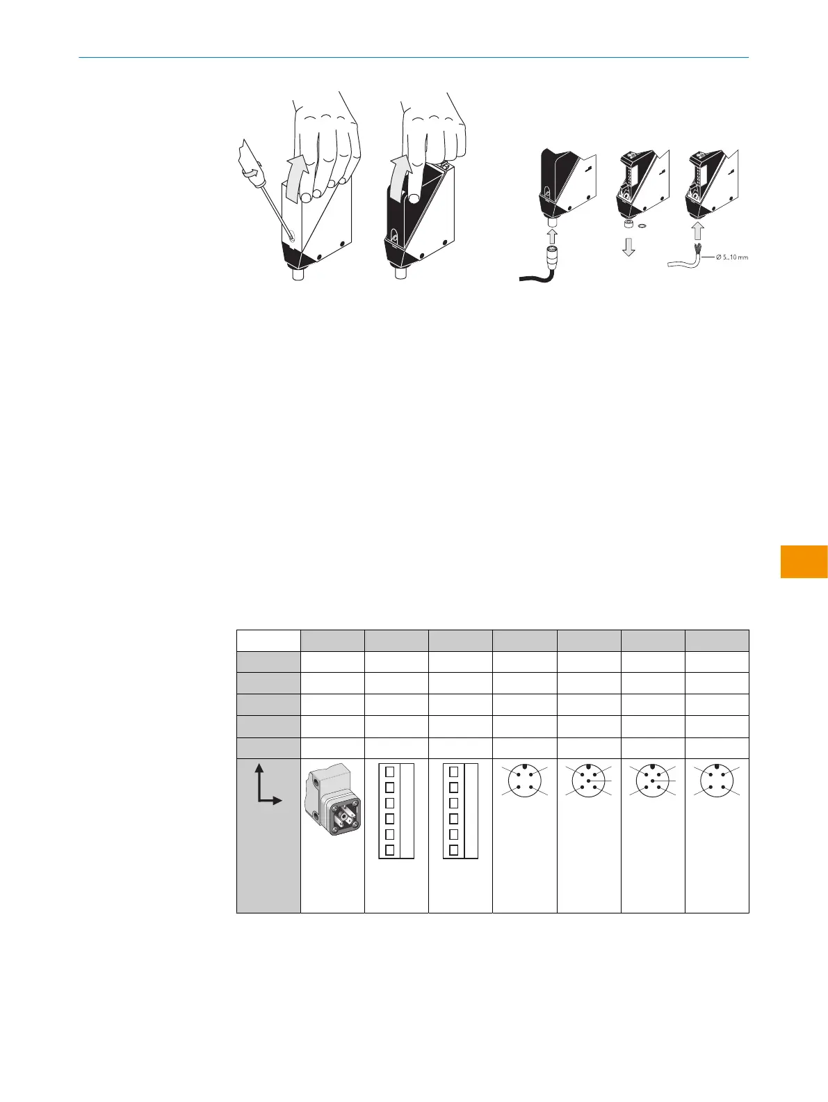
Figura 1: Aprire il sensore Figura 2: Allacciamento elettrico
Solamente in seguito alla realizzazione di tutti i collegamenti elettrici, ripristinare o
accendere l’alimentazione di tensione.
Spiegazioni sullo schema di collegamento (tabelle 2-7) che sono suddivise in dispositivi
DC e AC/DC:
Allarme = uscita allarme (vedi tabella 38 e Funzioni supplementari)
n. c. = non collegato
N/C
N/O
Q / Q = uscite di commutazione
TE/Test = entrata di prova (vedi tabella 38 e tabella 43)
5.1
WT24-2Bxxx, WT24-2Vxxx
U
B
: 10 ... 30 V DC, v. „Dati tecnici“, pagina 78
Tabella 2: DC
WT24-2 B3x3 B2x0 V2x0 B4x0 V5x0 V510S15 B410S25
1 + (L+) + (L+) + (L+) + (L+) + (L+) + (L+) + (L+)
2 - (M) - (M) - (M) Test Test Allarme n. c.
3
Q/Q
- Allarme - (M) - (M) - (M) - (M)
4 -
Q/Q Q/Q Q/Q Q/Q Q/Q Q/Q
5 - Test Test - Allarme Test -
I
N
= 4 A
0,14 ...
1,5 mm
2
I
N
= 4 A
0,14 ...
1,5 mm
2
I
N
= 4 A
ISTRUZIONI PER L'USO
8008784.1DMA/2022-07-12 | SICK I S T R U Z I O N I P E R L ' U S O | WT24-2
71
Contenuti soggetti a modifiche senza preavviso
it