Connecting
6.1 Electrical connection
Synchronous Motors 1FK7
34 Operating Instructions, 03/2011, 610.40700.40c
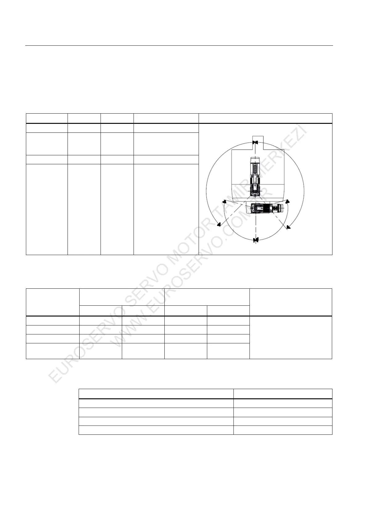
Ability to rotate the connectors for motors without a DRIVE-CLiQ interface and for motors with DRIVE-
CLiQ interface via Sensor Modules
1FK7□□□-□□□□□-□X□□; X = A, E, H, D, F, L
Table 6- 5 Rotation range of the power connector
Motor Angle α Angle β Connector size Drawing
1FK703 122° 158° 1
1FK704
1FK706
1FK708
135°
140°
1
1FK710 135° 195° 1
1FK708
1FK710
195° 140° 1.5
˞
ಬ
Table 6- 6 Rotation range of the signal connector
with DRIVE-CLiQ via Sensor
Module
connector without DRIVE-CLiQ
Motor
Angle α´ Angle β´ Angle α´ Angle β´
Drawing
1FK703 160° 130° 160° 135°
1FK704 145° 140° 145° 130°
1FK706 140° 145° 150° 135°
1FK708
1FK710
105° 100° 105° 105°
See Table, "Power connectors"
Table 6- 7 Max. torque when rotating
Connectors Max. torque when rotating
Power connector, size 1 12 Nm
Power connector, size 1.5 20 Nm
Signal connector (without DRIVE-CLiQ) 12 Nm
Signal connector (with DRIVE-CLiQ) 8 Nm
EUROSERVO SERVO MOTOR TAMİR MERKEZİ
WWW.EUROSERVO.COM.TR

 Loading...


