Description
3.4 Structure
1FT7 synchronous motors
Operating Instructions, 04/2010, 610.40075.40b
19
Forced ventilation
This cooling method is implemented by means of a separate ventilation module equipped
with a ventilator that operates independently of the motor. The fan is available with degree of
protection IP54.
NOTICE
Steps must be taken to ensure that the motor is always operated in conjunction with the
separately driven fan.
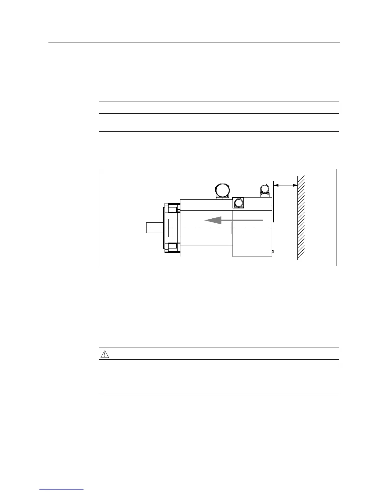
The motors must be arranged in such a way that the cooling air can flow in and out without
obstruction and that the minimum clearance s between the inlet/outlet air openings and
adjacent components is maintained (see "Minimum clearance" diagram below).
V
s A minimum clearance of 30 mm applies for AH 63 and AH 80.
A minimum clearance of 50 mm applies for AH 100.
Figure 3-2 Minimum clearance s
Steps must be taken to ensure that hot outlet air cannot be drawn back into the system. The
direction of air flow is from the non-drive end (NDE) to the drive end (DE). The fan may only
be operated with normal ambient air, as air containing chemical or conductive impurities
could cause the fan to fail prematurely. Deposits from contaminated air could result in poor
heat transfer at the motor or could cause the cooling-air duct to become clogged, leading to
an overheated motor.
WARNING
Danger of being drawn into the machine
There is a danger of being drawn into the machine (by means of hair, ties, loose items, etc.)
at the air inlet. Suitable protective measures must be taken to guard against this: wear a
hairnet, take off ties, keep clear of the intake area, etc.