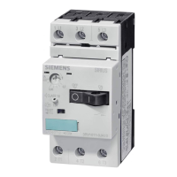
23 – 19 3ZW1012-0WL11-0AB1
Obere Festkontakte ausbauen
1 Schrauben und Muttern entfernen
2 Festkontakt herausziehen
Untere bewegliche Kontakte ausbauen
1 Anschlussschienen abstützen
2 Koppelbolzen herausdrücken
3 Koppelbolzen entnehmen
4 Strombahnen abnehmen
23.4.4 Strombahnen einbauen
Obere Festkontakte in Rückwand einbauen
1 Nur Baugröße I: Schrauben der Leithörner lösen
2
Kontakt einsetzen und Vierkantmutter in Ausnehmung einlegen
3 Kontakte befestigen;
Schrauben der Leithörner mit 10 Nm nachziehen;
Nur Baugröße I:
Leithorn gerade an das Schaltergehäuse an-
drücken und mit 15 Nm festziehen
Removing upper fixed contacts
1 Remove bolts and nuts
2 Remove fixed contact
Removing lower moving contacts
1 Support connecting bars
2 Push out coupling bolt
3 Take coupling bolt out
4 Remove pole assemblies
23.4.4 Installing pole assemblies
Installing upper fixed contacts in rear wall
1 Only frame size I: Undo screws of guide horns
2 Mount contact and insert square nut in recess
3 Fix contacts
Re-tighten screws of guide horns with 10 Nm;
Only frame size I:
press guide horn straight against the circuit
breaker housing and tighten with 15 Nm
3
Gr. / Size
5
10 Nm
BG I / FS I:
15 Nm
 Loading...