12-4
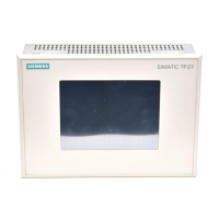
TP27, TP37 Equipment Manual
Release 01/00
It must be ensured that the threaded spindles of the screw-type clamps are
tightened with the recommended torque of 0,5 Nm.
After correct fixing of the equipment, the seal remains visible owing to
construction reasons.
!
Caution
Do not try to upset the seal until the TP27-10 and the front panel lie on each
other at the same level.
Any damages caused by too high torques when tightening the screw-type
clamps of the TP27-10 are not covered by the warranty.
Maximum torque
Seal
Installation

 Loading...


