18-1
TP27, TP37 Equipment Manual
Release 01/00
Maintenance/Upkeep
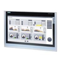
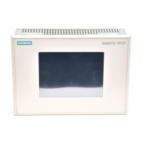
The Touch Panels TP27 and TP37 are designed for low maintenance operation.
Maintenance of the TP is limited to
S regular cleaning of the screen
S changing the backup battery and
S replacing the LCD back–lighting (TP37 only).
18.1 Cleaning the Screen
Clean the Touch Panel screen at regular intervals using a damp cloth. Do not
clean the TP while it is turned on. Either switch the unit off or deactivate the
Touch Screen. The way to deactivate the Touch Screen is described in Sec-
tion 11.3. This ensures that functions are not triggered by inadvertently coming
into contact with the touch screen.
Use only water or a screen cleaning foam to dampen the cloth. Do not spray
cleaning agents directly onto the screen, but onto the cloth. Never use aggres-
sive solvents or scouring powder.
The protective foil for the TP prevents the screen being scratched or soiled. It
is available as an option at your local Siemens branch.
Scope
Preparation
Cleaning agents
Protective foil
18

 Loading...


