17-9
TP27, TP37 Equipment Manual
Release 01/00
17.2.2 Connectors
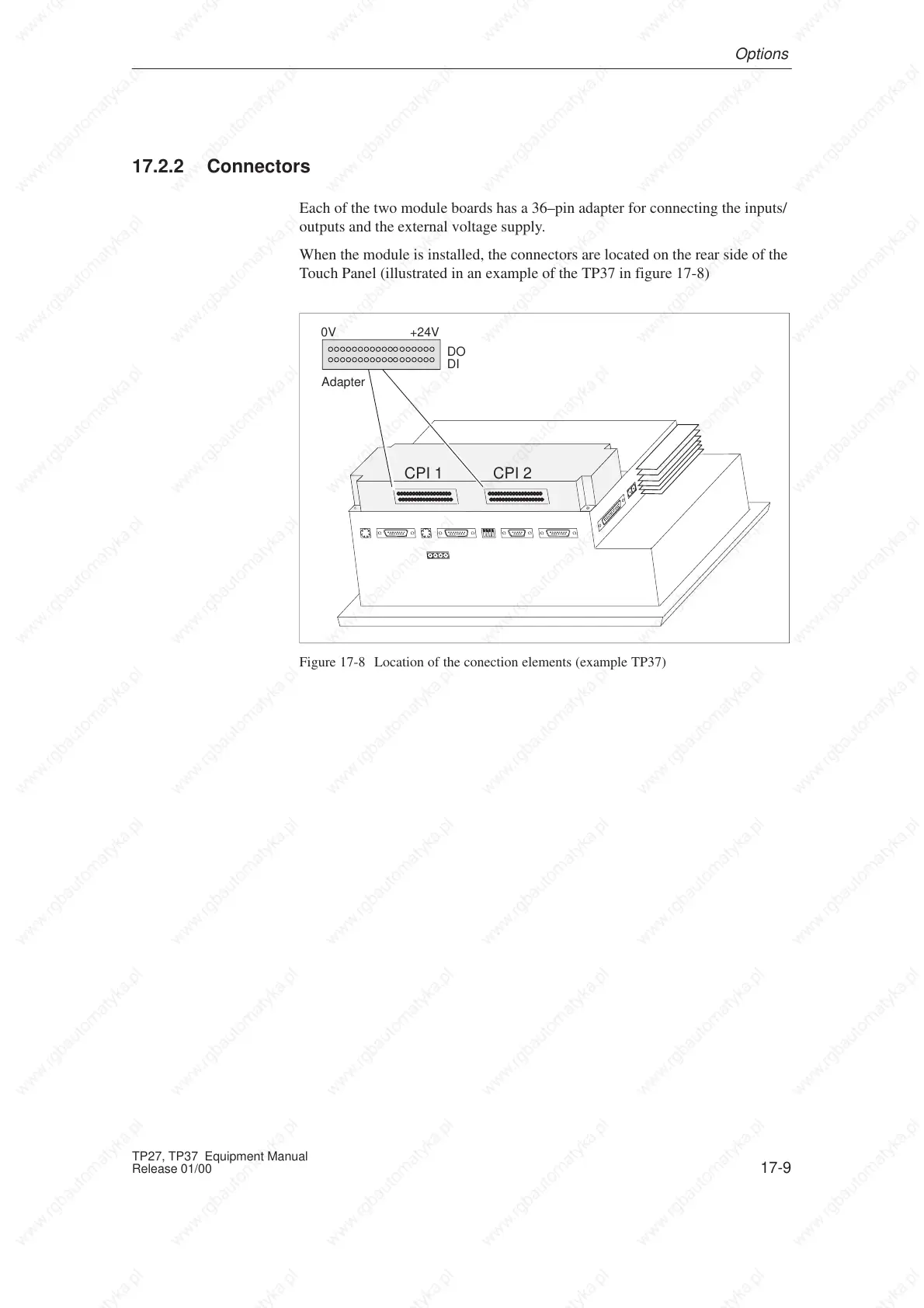
Each of the two module boards has a 36–pin adapter for connecting the inputs/
outputs and the external voltage supply.
When the module is installed, the connectors are located on the rear side of the
Touch Panel (illustrated in an example of the TP37 in figure 17-8)
DKM A
DKM
B
CPI 1
0V +24V
Adapter
DO
DI
CPI 2
Figure 17-8 Location of the conection elements (example TP37)
Options
 Loading...