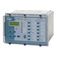
7SR224 Argus Installation
Contents
Section 1: Installation............................................................................................................................................... 3
1.1 Unpacking, Storage and Handling .......................................................................................................... 3
1.2 Recommended Mounting Position .......................................................................................................... 3
1.3 Wiring...................................................................................................................................................... 3
1.4 Earthing................................................................................................................................................... 3
1.5 Ancillary Equipment ................................................................................................................................3
1.6 Equipment Operating Conditions Current Transformer Circuits .............................................................. 3
1.7 Fibre Optic Communication..................................................................................................................... 4
1.8 Front Cover ............................................................................................................................................. 4
Section 2: Dimensions and Panel Fixings................................................................................................................ 5
2.1 Relay Dimensions and Weight ................................................................................................................ 5
2.2 Fixings..................................................................................................................................................... 6
2.2.1 Crimps....................................................................................................................................... 6
2.2.2 Panel Fixings ............................................................................................................................ 6
2.2.3 Fibre Optic Connectors ............................................................................................................. 6
Section 3: Rear Terminal Drawings ......................................................................................................................... 7
3.1 E10 Case ................................................................................................................................................ 7
Section 4: Connection/Wiring/Diagrams .................................................................................................................. 9
4.1 Wiring Diagram: 7SR224 Recloser Controller Relay............................................................................... 9
4.2 Interface Diagram: 7SR224 Recloser Controller Relay ......................................................................... 11
Section 5: Data Comms Connections .................................................................................................................... 12
5.1 RS485 Connection ................................................................................................................................12
5.2 RS232 Connections .............................................................................................................................. 13
5.3 IRIG-B Connections .............................................................................................................................. 13
5.4 Fibre Optic Connections........................................................................................................................ 13
Section 6: Connection Diagrams............................................................................................................................ 15
6.1 Typical A.C. Connections: 7SR224 DOC/DEF Recloser Control Relay ................................................ 15
List of Figures
Figure 4.1-1 Wiring Diagram: 7SR224 .....................................................................................................9
Figure 4.1-2 Additional Inputs & Outputs Wiring Diagram: 7SR224 ......................................................10
Figure 4.2-1 Interface Diagram: 7SR224 ...............................................................................................11
Figure 5.1-1 RS485 Data Comms Connections Between Relays..........................................................12
Figure 5.4-1 Data Comms to Multiple Devices Using Sigma 1 and F.O. Star Network .........................13
Figure 5.4-2 Data Comms to Multiple Devices Using Sigma 3 and F.O. Ring Network ........................14
Figure 6.1-1 7SR224 Connections to OHL Circuit .................................................................................15
Figure 6.1-2 7SR224 Connections to OHL Circuit with Core Balance CT .............................................16
©2010 Siemens Protection Devices Limited Chapter 5 Page 2 of 16

 Loading...


