Installation
64/214 Revision 11 • INSTALLATION AND OPERATING INSTRUCTIONS • 8DA10 • 861-9601.9
➭ Clear the assembly opening ② : Remove all horizontal flange covers on the busbar
housing ① of the fixed-mounted panel.
➭ Undo the busbar ⑤ at the joint ③ in the busbar housing through the assembly opening ② .
The busbar support ⑩ remains in the disassembled busbar section.
➭ Take the busbar section ⑤ with the busbar support ⑩ out of the housing through the
vertical flange ④ .
➭ Through the vertical flange ⑨ , push the busbar section ⑤ into the busbar housing ⑦ of
the panel to be lined up
➭ Clean the links at the busbar sections using an emery sponge and a lint-free cloth.
Then, apply a very thin film of the supplied mounting paste.
➭ Assemble the busbar section at the joint ⑧ .
➭ Check alignment and parallel position of the assembled busbar section,
and correct if required.
Special configurations of the interconnected busbar
Preparing the flanges of the busbar housings
➭ Clean all vertical flanges of the busbar housings at the panel joint and the grooves for
the toroidal sealing rings (O rings) carefully with lint-free paper.
➭ Carefully check the sealing surfaces ③ of the flanges for scratches, other damages or
pollution. Damages and pollution will cause leaks.
➭ If the sealing surfaces ③ are damaged: Inform the regional Siemens representative and
coordinate the elimination of damages.
➭ Grease the toroidal sealing rings ② uniformly with the supplied mounting paste
(Polylub GLY 801).
➭ Apply a layer of mounting paste (Polylub GLY 801) with a thickness of approx. 3 mm all
around on the external contact surfaces of the flanges.
➭ Distribute the mounting paste (Polylub GLY 801) evenly on the external contact surfaces ①
with a fine line brush.
➭ Lay the toroidal sealing rings (O-rings) into the grooves of the flanges.
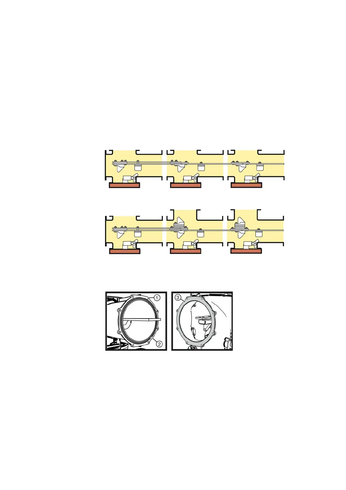
Fig. 44: Busbar assembly, left end panel (example: 1250 A)
Fig. 45: Busbar assembly, left end panel, adjacent panels with disconnectable busbar
components (example: 1250 A)
Fig. 46: Flange on the busbar housing
①
External contact surface of
the flange
②
Groove for toroidal sealing ring
③
Sealing surface at
the opposite flange

 Loading...


