Installation
66/214 Revision 11 • INSTALLATION AND OPERATING INSTRUCTIONS • 8DA10 • 861-9601.9
Preparing busbar assembly for 4000 A busbar version
Fig. 48: Busbar version 4000A
For other disconnectable components, e.g. make-proof busbar earthing switch, the busbar
joints are not accessible anymore after the transport units have been interconnected.
For further information, please contact the Siemens Service Hotline.
INFORMATION
Execute this installation section only if one of the following devices is mounted on
the busbar housing of the panel to be lined up for a 4000 A busbar:
• Disconnectable busbar connection
• Disconnectable busbar voltage transformer
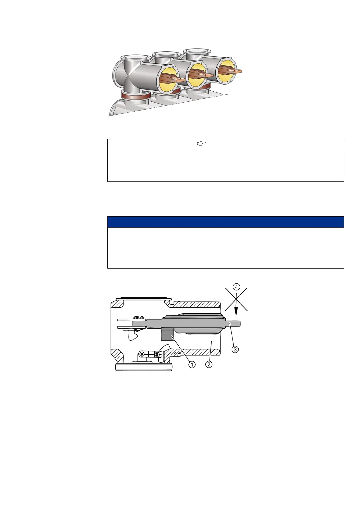
NOTICE
Damage to the busbar support
The busbar support keeps the busbar with a weight of approx. 26 kg in the correct
position for the busbar connection.
➭ After removal of the transport block, do not exert any force on the busbar in order not to
damage the busbar support.
Fig. 49: 4000 A busbar without transport block
①
Busbar support
②
Busbar housing
③
Busbar
④
Force in kg

 Loading...


