Installation
68/214 Revision 11 • INSTALLATION AND OPERATING INSTRUCTIONS • 8DA10 • 861-9601.9
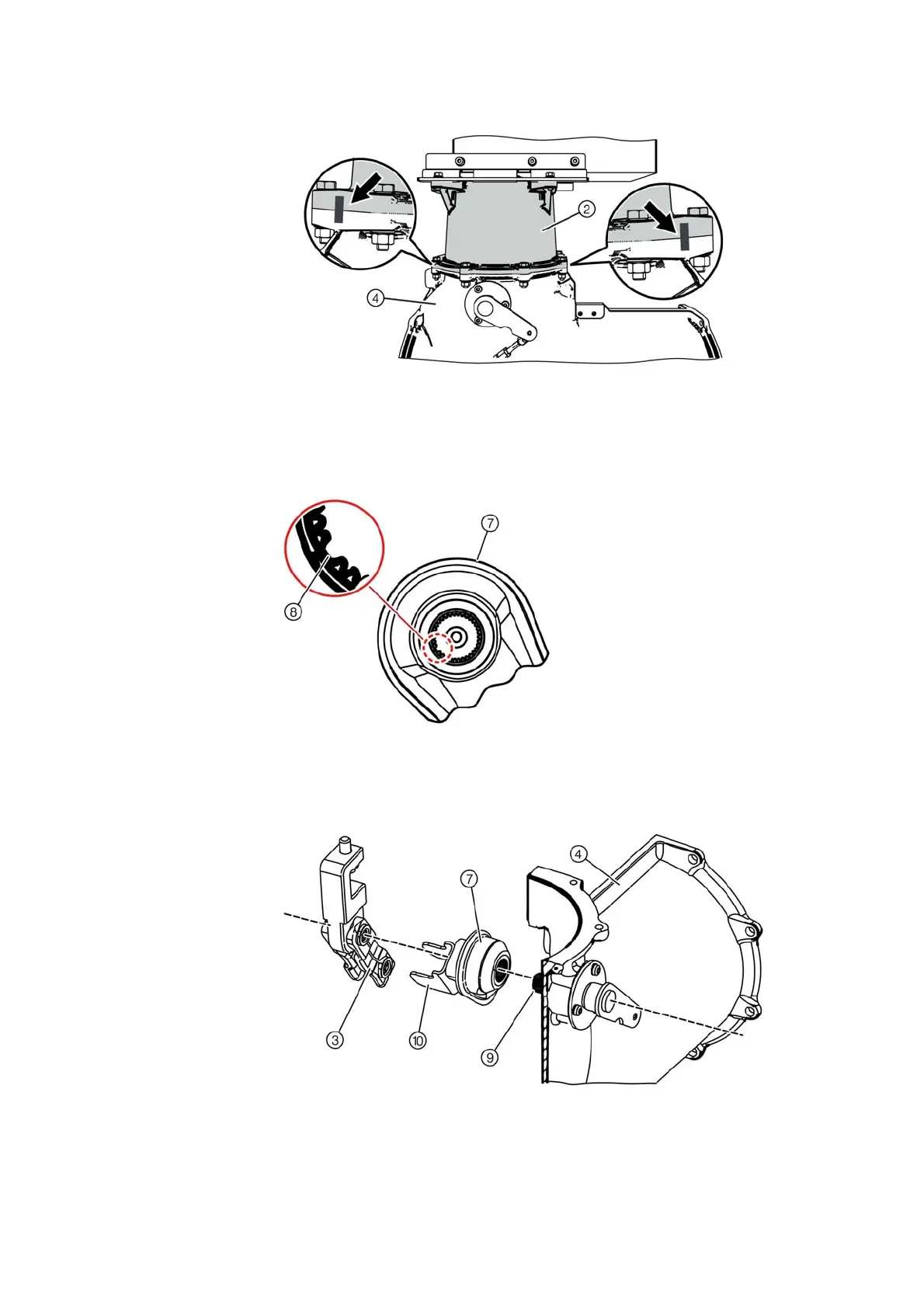
➭ Mark the position from the transformer connection housing ② to the busbar housing ④ by
two lines offset by 90°. The lines serve as positioning aid for later assembly.
Fig. 52: Positioning aids (zooms show side views)
➭ Remove the bolted joint ⑥ between the transformer connection housing ② and the busbar
housing ④ . Remove the intermediate ring with supporting plate and disconnector.
The disconnector kinematics of the disconnectable voltage transformer with the short
disconnector shaft remain mounted.
➭ Pull the rotary post insulator ⑦ off the disconnector shaft.
➭ Loosen the fixing bolts at the busbar ends.
Fig. 53: Coding at the rotary post insulator
⑦
Rotary post insulator
⑧
Coding (slot)
The coding at the rotary post insulator helps
to position the component correctly during
later installation.
Fig. 54: Setup of the voltage transformer disconnector at the busbar
③
Disconnector
⑩
Driver
⑦
Rotary post insulator
⑨
Disconnector shaft
④
Busbar housing

 Loading...


