861-9601.9 • INSTALLATION AND OPERATING INSTRUCTIONS • 8DA10 • Revision 11 69/214
Installation
Example: Assembling
top units for
busbar voltage
transformer 4MU4
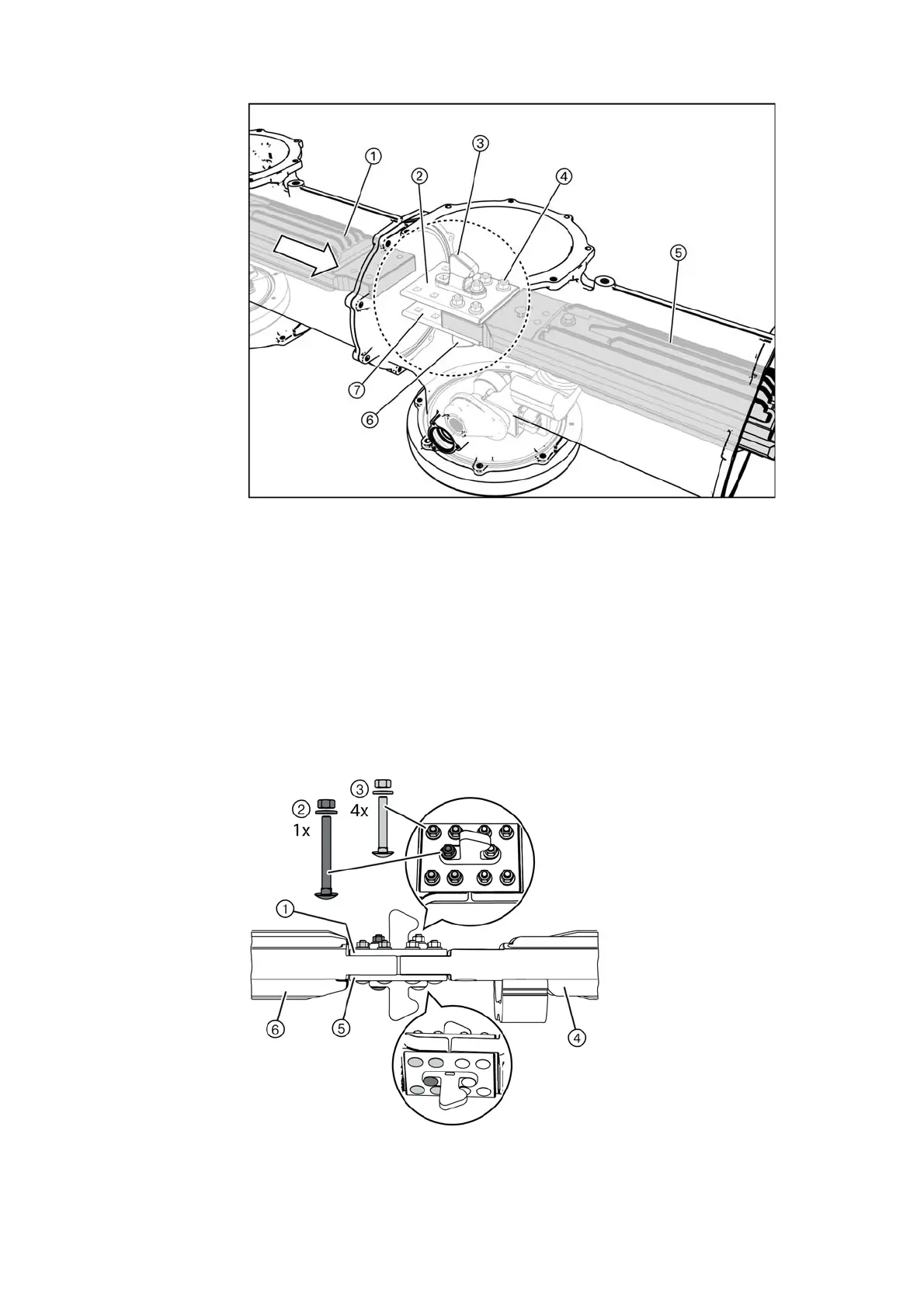
➭ Prepare the flanges of the busbar housing, and bolt them together.
➭ Align the busbar and the connecting bars so that the busbar section is in line and the bolts
fit through the hole.
➭ Tighten the bolts in this busbar section (tightening torque: 40Nm).
Fig. 55: Inserting the busbar
①
Busbar in the fixed-mounted panel
②
Upper connecting bar
③
Upper disconnector contact
④
Cup head bolt with hexagon nut and conical spring washer (5x)
⑤
Busbar in the panel to be lined up
⑥
Lower disconnector contact
⑦
Lower connecting bar
Fig. 56: Bolting the busbar and the connecting bars
together
①
Upper connecting bar
②
Cup head bolt with hexagon nut
and conical spring washer
M10x85 (1x)
③
Cup head bolt with hexagon nut
and conical spring washer
M10x65 (4x)
④
Busbar in the panel to be lined
up
⑤
Lower connecting bar
⑥
Busbar in the fixed-mounted
panel

 Loading...


