Installation
94/214 Revision 11 • INSTALLATION AND OPERATING INSTRUCTIONS • 8DA10 • 861-9601.9
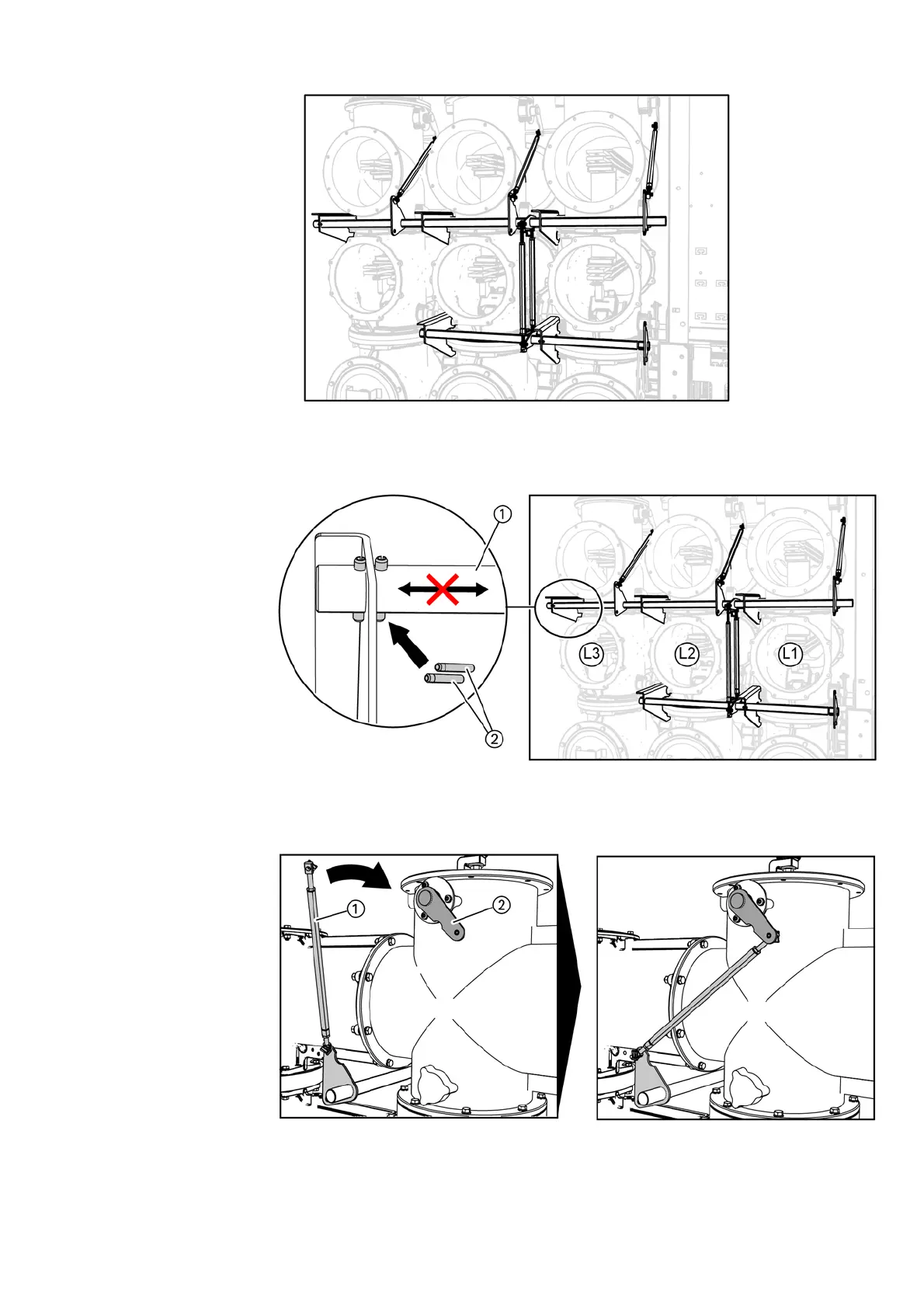
Fig. 105: Mounting position of kinematic system at the upper and lower busbar housings
➭ Secure the rear end of the operating shaft ① with spring-type straight pins ② to prevent
displacement of the operating shaft.
Fig. 106: Securing the operating shaft
➭ Hook the coupling rod ① in at the lever of the disconnector shaft②
(upper busbar housing).
Fig. 107: Fixing the coupling rod at the upper busbar housing
➭ Checking contact overlapping of disconnector contacts and adjust, see page 74,
"Completing switchgear installation".
 Loading...


