Installation SD39EAM-1r4
2-14 September 2005
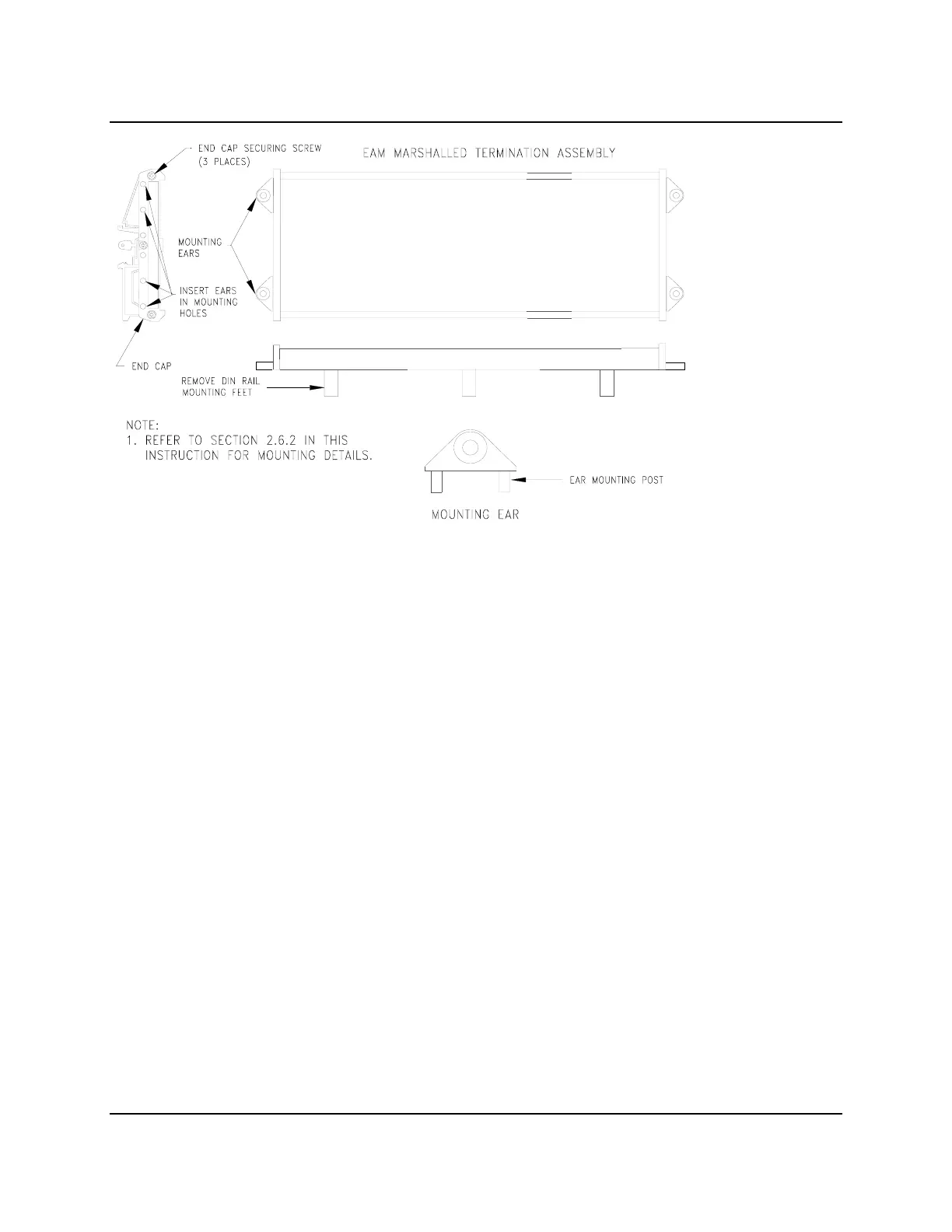
Figure 2–6 EAM Marshalled Termination Assembly Flat Surface Mounting
2.6.3 Cable Installation
An Interconnect I/O Cable (Figure 2-7) is used to connect each EAM to an EAM Marshalled Termination
Assembly when remote I/O termination is employed. Install cable-to-module connector J1 at the
MODULRAC slot location of an EAM. It is assumed that as part of the site preparation procedure all
tagged Interconnect I/O Cables have been routed and pulled into their respective cabinets and are ready
for connection. EAM Marshalled Termination Assemblies should already be installed in the marshalling
cabinet (see section 2.6.1) and be ready for cable connection. An Unterminated I/O Cable is installed
similarly at the MODULRAC; however, terminations in the marshalling cabinet are user supplied.
1. Note the following on the cable’s J1 connector.
• The lower face of the molded connector has a “pin mounting hole” located above a captive
mounting screw. This hole engages one of the MODULRAC Panel’s ten alignment pins.
• The top edge of J1 will rest in the groove of the backplane’s extruded spacer as illustrated by a
detail in Figure 2-2.
2. Consult user documentation and note the MODULNET node address (if any), MODULRAC address
number (1 to 16) and slot number (1 to 10) assigned to the EAM. J1 will be mounted at this location.