SD39EAM-1r4 Maintenance
September 2005 3-3
3.4 Troubleshooting
Errors are annunciated by:
• The module’s status LEDs (see Table 3-1)
• The 4-mation configuration software - Error codes and messages; refer to Diagnostic Error Codes
and Software Messages (document number CG39-19) or 4-mation’s help file.
The 4-mation configuration software runs on an IBM-compatible PC or the APACS+ Rack-mounted
Industrial Server (RIS).
Module status LEDs are located on the EAM’s bezel. Note LED indications, then refer to Table 3-1 for
EAM status and 4-mation to determine the course of action.
Interconnect I/O Cable pin assignments are listed in Table 2-3. These are provided for troubleshooting a
suspect cable.
As necessary, check field wiring and field-located devices.
The EAM, Termination Strip, and Marshalled Termination Assembly are not field serviceable, except for
the EAM power fuse replacement. A failed assembly should be returned to the factory for repair.
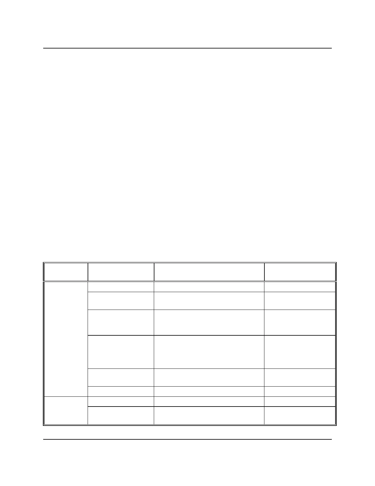
Table 3–1 LED Status Indications
LED
INDICATOR
LED
INDICATION
MODULE STATUS USER ACTION
Solid Green Module OK; Configured with no faults ---
Flashing Green/ Black Module Not Configured; No fault or
failure
Configure module
Flashing Red/Green Fault Detected; One or more channel
specific errors, or a less severe board
level error
Replace module or
channel fuse
Flashing Red/Black (1
per second)
1. Low or defective I/O supply
2. Failure Detected; Board level
problem
affecting more than one channel
Replace module
Flashing Red/Black (5
per second)
IOBUS Communication Error 1. Check ACM
2. Replace module
OK
Solid Red Module Fault, Severe Replace module
Solid Green Module in Control --- ACTIVE
OFF Redundant EAM in Standby Mode or
off-line configuration of module
---