Circuit Description SD39EAM-1r4
4-6 September 2005
Board Problems
• Backplane Power Failure
• Internal Module Overtemperature
• RAM Checksum
• ROM Checksum
• Redundancy Switch-Over
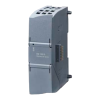
An OK LED and an ACTIVE LED on the module’s bezel provide a local indication of the following
module status:
• Module OK
• Channel(s) Faulted
• Module Faulted
• Module Not Configured
• IOBUS Communication Fault
• Module Active (Redundancy Primary)
• Module Inactive (Redundancy Backup)
The OK LED is the principal error annunciator. At initial turn on, the EAM’s CPU uses a common start
up routine to perform certain self-diagnostics, such as ROM and RAM tests, and to setup specific board
functions. If the common start up routine is successful, the OK LED will be set to a solid green color and
the EAM begins to execute common I/O board diagnostics; if not successful, the OK LED will be set to a
flashing red color at a 1 second flash rate.
The ACTIVE LED lights to a solid Green if the module is enabled. A redundant EAM in the standby
mode will show a solid Green OK and Black (OFF) ACTIVE LEDs.
All errors generated by the diagnostics are reported to the control module (ACM), which maintains a
current error log that can be accessed by any APACS+ operator interface or the 4-mation configuration
software. The 4-mation software also provides additional diagnostic and status displays.
 Loading...


