4.3 Designing the pipe system
Take the following into account for an effective design:
● Pipe length
● Number of aspirating holes
● End cap hole
● Number and radius of bends
● Number of pipes
● Length of capillary tubes
● Size of bends and branches
● Differences in air pressure
● How the total airflow is split into separate airflows for each pipe
● Equalization of airflows in the pipes
● Response time, i.e., the time it takes to transport air to the aspirating smoke
detector from aspirating holes that are far away
● Sensitivity of the aspirating holes
● Total power of the system including all components
● End caps with holes at the end of the pipes are used to adjust the airflow
● Filter box and its effect on the airflow (must be taken into account in the
software 'FXS2056 ASD Asyst‑Tool V3')
● The air return pipe must be kept as short as possible so as not to impair the
aspirator.
4.4 Planning the pipe system
w You are familiar with the function of the aspirating smoke detector and the local
conditions.
◈
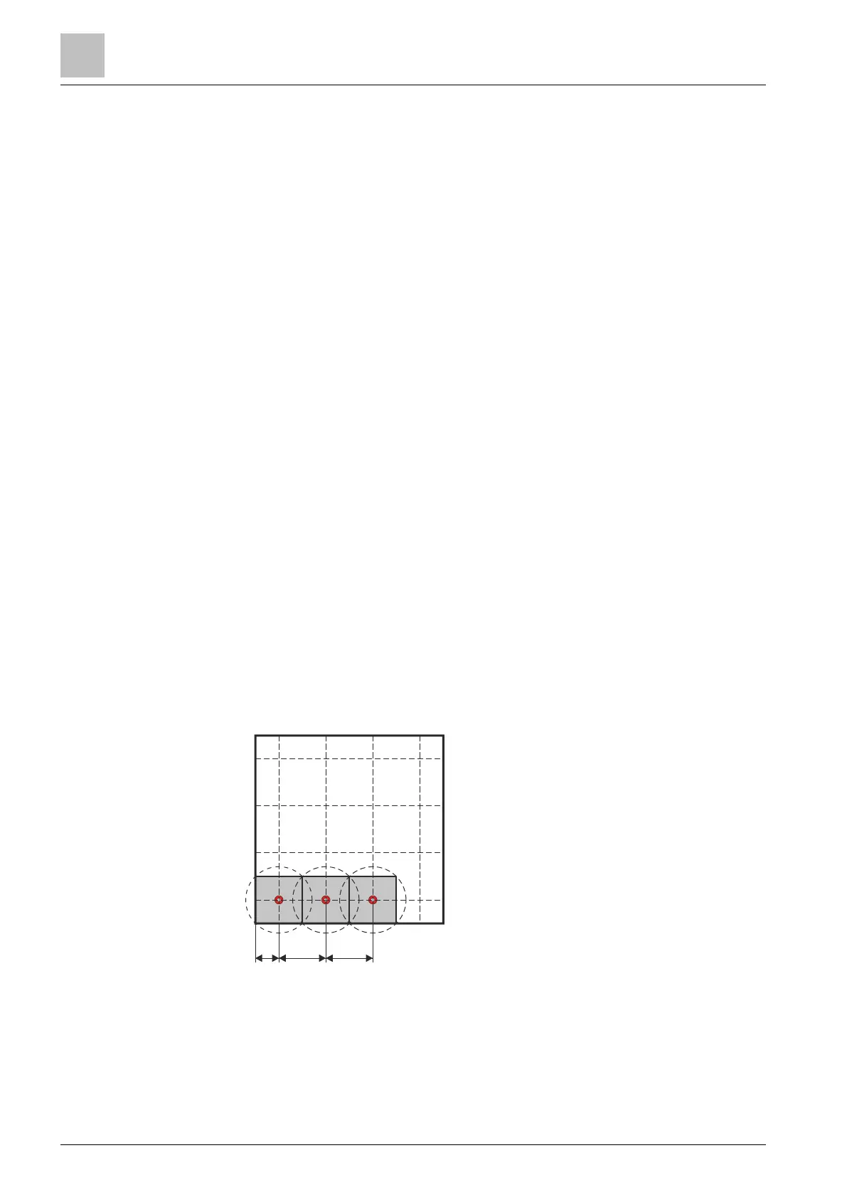
Spread the aspirating holes throughout the room like the nodes in a network.
– Typical mesh sizes are 3x3m, 4x4m, and 6x6m.
– The maximum gap(A) from the wall to the nearest aspirating hole is
defined in local regulations and guidelines.
– The maximum gap(B) between two aspirating holes is 10m.
Fig. 11: Planning the pipe system
a The network of aspirating holes has been created.
Planning
Designing the pipe system
4
28 | 48 A6V11783979_en--_a
 Loading...